| View previous topic :: View next topic |
| Author |
Message |
madmike
Member

Joined: Apr 08, 2009
Posts: 249
Location: Mariposa, Ca.
|
 Posted: Fri Apr 05, 2013 4:11 pm Post subject: Distributor Problems Posted: Fri Apr 05, 2013 4:11 pm Post subject: Distributor Problems |
 |
|
After working on this M38A1 restoration for three years and 1 and one half weeks away from Camp Delta, I now find that the distributor is worn out on two lobes. My bad but a new one from Midwest is about $600 with shipping and tax or I can have mine rebuilt and miss Camp Delta.
One thought mentioned was maybe to find a good distributor shaft and trade it out. Any thoughts on this? After all the money I spent on this restoration I hate to go on the cheap but I am in need and cannot run the A1 with the current distributor. Apparently no kits are available.
Any ideas/options out there? If I could get ignition there might more problems to keep me away but I won't know that until lift off.
Mike |
|
| Back to top |
|
 |
Bill_F
Member

Joined: Apr 17, 2005
Posts: 891
Location: New Hampshire
|
| Posted: Fri Apr 05, 2013 4:17 pm Post subject: |
|
|
| The lobes come off the dist so as long as you can find a replacement one you should be fine. I might have a spare. I will have to look. How is the shaft in yours? Are the bushings still good? |
|
| Back to top |
|
|
madmike
Member
Joined: Apr 08, 2009
Posts: 249
Location: Mariposa, Ca.
|
| Posted: Fri Apr 05, 2013 6:55 pm Post subject: |
|
|
The shaft seems tight but I now notice one more problem and I don't know if it's the distributor or the pump. I was/am having trouble engaging the distributor in the pump. The dist. is bottom out and no lock up on the rotor. So I measured and the shaft appears to be short and only long enough to barely engage the pump according to the wear marks.
The overall shaft is 12 inches long and 7 7/8 inches from the base to the tip of the shaft. If you have a measurement on that spare I would like to confirm. I looked at the blowup of the pump and I don't see shims or anything that would cause a short shaft situation. The number on my dist. is consistent with the manual so I don't believe I have an incorrect part.
I did note that on epay there is a rebuild kit to include the bushings if I need them. A new/used lobe would be great but I sure would like a little more "hook up" on that shaft.
Besides all this, I found that the position of the dist shaft is different than the book when in the firing position for No.1. I have to place it at 9 oclock to have it positioned correctly. Since I know I am at TDC, it should not be a problem but I don't know why that would be different from the manual.
If I can get a part to make this run for the meet it would be fantastic. Even if a used part. That would give me time to research this or have my dist rebuilt after the meet. |
|
| Back to top |
|
|
wesk
Site Administrator


Joined: Apr 04, 2005
Posts: 16256
Location: Wisconsin
|
|
| Back to top |
|
|
madmike
Member
Joined: Apr 08, 2009
Posts: 249
Location: Mariposa, Ca.
|
| Posted: Fri Apr 05, 2013 11:53 pm Post subject: |
|
|
Yes, is the short answer. And I can see that the wear on the shaft shows that it has been barely engaged for some time. It appears to be riding about 1/8th of an inch onto the end. I did have it engaged when the engine was out of the vehicle and I was finishing the assembly. I got it back as a short block from the builder.
I have an indexing problem too. I have the engine at top dead center and the pump at 1100 as the book shows. But when I look at the distributer shaft, it is at 2100 when the rotor is pointing to #1. Unless I put the pump at 2100, I will not be able to get the engine to fire #1 at the correct time.
The engine builder lost my original timing pointer and a replacement was found and appears to be correct but when the piston is at TDC, the mark on the pulley is about 10 degrees before the 5 degree mark. It's all very confusing but I am guessing that if I can get the distributer on #1, at TDC, I can adjust my mark or vacuum time the engine.
I will add too, that the engine ran but not well when I purchased it. No kidding with that distributor. So I know it will engage, but just barely. |
|
| Back to top |
|
|
wesk
Site Administrator
Joined: Apr 04, 2005
Posts: 16256
Location: Wisconsin
|
| Posted: Sat Apr 06, 2013 8:36 am Post subject: |
|
|
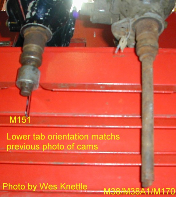
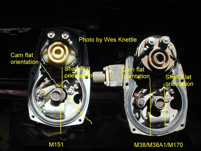
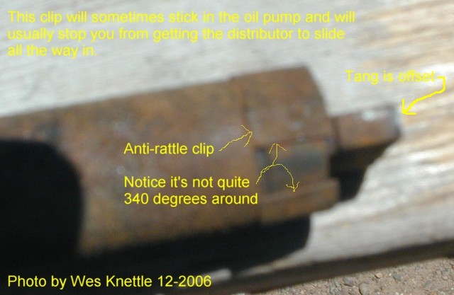
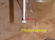
There are several issues that will limit engagement between the distributor shaft and the oil pump shaft. A too thick home made gasket on the oil pump and/.or the distributor base. The anti-rattle or friction clip at the bottom of the distributor shaft can separate from the shaft on removal staying down on top of the pump shaft and then later limits how far down the distributor shaft can go. Mixing of components on a distributor can give a person grief to. IE the M151 unit rotates opposite the Willys units and the cam is indexed to the shaft differently. Using a M151 cam will really mix things up.
Timing is a tricky proposition from the get/go but if you don't have a reliable 5 degree BTDC mark and pointer you are shooting in the dark. The only way to set up a preciously booggered up setup is to start at the beginning.
With #1 piston TDC on compression stroke and the timing gear marks aligned on the cam and crank gears. If you don't want to pull the crank pulley and timing cover then adapt a dial indicator to the #1 spark plug hole and measure to find the piston at TDC. Remember there's a short flat spot in crank rotation where the piston does not move up or down for about 3 to 5 degrees. You slowly bring the piston up untill there no more increase on the dial indicator and stop. Make a crayon mark on the crank pully that aligns with your timing pointer. Now very slowly continue rotating the crank in the same direction until the instant the dial indicator starts to decrease it's reading and stop. Make a second crayon mark on the crank pulley in line with your timing pointer. Now make a mark halfway between the two crayon marks (small circumference section of the pulley). Now erase the first two marks. Set your new TDC mark in alignment with your timing pointer. Make a permanent notch in the pulley. This is your TDC. Now use a degree wheel to back the crank pulley up 5 degrees and make your ignition timing notch in your pulley. Voila you now have permanent reliable timing marks.
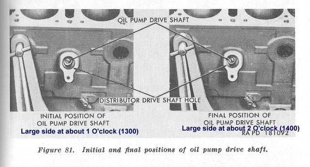
Now go back to the book and set the pump in it's correct index position.
Now before you try to guess the correc t position of #1 plug wire on your distributor I caution you to read the two changes to TM 9-8014 that warn you the original illustration in your TM 9-8014 is incorrect and they give you the correct position in the two changes. I am talking about figure 79 on page 173. That figure is WRONG.
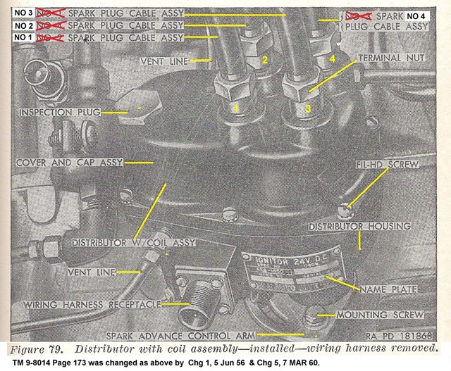
This is the corrected figure.
_________________
Wes K
45 MB, 51 M38, 54 M37, 66 M101A1, 60 CJ5, 76 DJ5D, 47Bantam T3-C & 5? M100
Mjeeps photo album: http://www.willysmjeeps.com/v2/modules.php?set_albumName=Wes-Knettle&op=modload&name=gallery&file=index&include=view_album.php |
|
| Back to top |
|
|
madmike
Member
Joined: Apr 08, 2009
Posts: 249
Location: Mariposa, Ca.
|
| Posted: Sat Apr 06, 2013 8:40 am Post subject: |
|
|
And I thought of something else inconsistent with the manual. The thicker part of the offset on the distributor shaft, when in the number one position, is down rather than up. Is it possible to set the shaft up with No.1 in a different position? I am thinking maybe someone had the unit apart, and maybe put a shorter shaft in and set it up wrong.
Mike |
|
| Back to top |
|
|
wesk
Site Administrator
Joined: Apr 04, 2005
Posts: 16256
Location: Wisconsin
|
| Posted: Sat Apr 06, 2013 8:48 am Post subject: |
|
|
The direction of the rotor in regards to #1 plug wire can be set anywhere by simply not indexing the pump shaft correctly. This can often work just fine as long as the selected pump indexing allows the distributor body enough rotation to correctly set the timing.
A short shaft is an extremely long odds possibility. Have you inspected for a detached friction clip lying down there on top of the pump shaft? Does your distributor shaft have the clip on it?
_________________
Wes K
45 MB, 51 M38, 54 M37, 66 M101A1, 60 CJ5, 76 DJ5D, 47Bantam T3-C & 5? M100
Mjeeps photo album: http://www.willysmjeeps.com/v2/modules.php?set_albumName=Wes-Knettle&op=modload&name=gallery&file=index&include=view_album.php |
|
| Back to top |
|
|
madmike
Member
Joined: Apr 08, 2009
Posts: 249
Location: Mariposa, Ca.
|
| Posted: Sat Apr 06, 2013 8:58 am Post subject: |
|
|
| Wes. I just read your reply and the spring is still in the correct place. The dist. bottoms out on the block. Your comment about the different clocking of the 151 dist. shaft makes me wonder if that is what happened with this unit. The dist. number is the same as what is in the manual so the original body is correct for this engine. But if the 151 shaft is about 1/4 inch shorter, this may explain the whole problem. Any idea how much shorter the shaft might be? |
|
| Back to top |
|
|
wesk
Site Administrator
Joined: Apr 04, 2005
Posts: 16256
Location: Wisconsin
|
|
| Back to top |
|
|
madmike
Member
Joined: Apr 08, 2009
Posts: 249
Location: Mariposa, Ca.
|
| Posted: Sat Apr 06, 2013 10:34 am Post subject: |
|
|
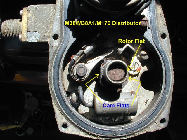
No one I know of is in my area with an A1 but I will check further on that and I am a member of West Coast Willys and will check them for a resource as well. I just looked again at your technical site and the picture you posted above shows there is no way this is a 151 shaft. Mine looks as it should.
But when I have the rotor flat in the position you show, the bottom of my shaft is oriented to 2000 and 0200, with the larger side of the slot to the 0200 side. The rotor contact is pointing straight down. Rotating that to the No 1 firing position, puts the shaft at 0900 and 1500, with the larger side of the shaft toward the bottom. That is not the same as what the manual says and that is why I asked if the shaft can be set up different than the book. Not having this apart, I don't know if the shaft can be assembled incorrectly. Any idea on that? |
|
| Back to top |
|
|
wesk
Site Administrator
Joined: Apr 04, 2005
Posts: 16256
Location: Wisconsin
|
| Posted: Sat Apr 06, 2013 11:23 am Post subject: |
|
|
To get us both on the same page lets start over.
1-Have you confirmed #1 is TDC on compression and the proper alignment of timing marks is set? (Note: Indexing pump and distributor is done with the #1 piston TDC not in the 5 deg. advanced firing position)
2-Have you confirmed the oil pump is the correct L & F134 pump and is installed correctly, with the correct thickness gasket (almost paper thin) and the correct indexing?
3-Does your distributor cam rotor flat align parallel with two of the cam flats? This is to confirm you have the correct cam on your distributor and has nothing to do with distributor indexing nor does the illustration have anything to do with distributor indexing.
_________________
Wes K
45 MB, 51 M38, 54 M37, 66 M101A1, 60 CJ5, 76 DJ5D, 47Bantam T3-C & 5? M100
Mjeeps photo album: http://www.willysmjeeps.com/v2/modules.php?set_albumName=Wes-Knettle&op=modload&name=gallery&file=index&include=view_album.php |
|
| Back to top |
|
|
madmike
Member
Joined: Apr 08, 2009
Posts: 249
Location: Mariposa, Ca.
|
| Posted: Sat Apr 06, 2013 11:45 am Post subject: |
|
|
| Yes on all three. But...If i were to install the distributor in that position, my rotor would be pointing at the 1600 position (roughly No. 3). That is why I asked if the shaft can be clocked/assembled differently to give you a different final position. It would seem the shaft is made one way and will only work one way. But I do not know that. |
|
| Back to top |
|
|
Bill_F
Member
Joined: Apr 17, 2005
Posts: 891
Location: New Hampshire
|
| Posted: Sat Apr 06, 2013 1:14 pm Post subject: |
|
|
| Someone could have put the came on 180 degrees out. |
|
| Back to top |
|
|
madmike
Member
Joined: Apr 08, 2009
Posts: 249
Location: Mariposa, Ca.
|
| Posted: Sat Apr 06, 2013 1:18 pm Post subject: |
|
|
I thought that could be the case but it does not appear to be 180 degrees. More like 120 degrees. But if it is possible to assemble it in differently, then maybe that is the case.
Bill..were you able to locate a used cam? I emailed you also. Thanks...Mike |
|
| Back to top |
|
|
|