It is interesting that OEM was "moving the bar" so to speak but I'd imagine if they began getting away from this early style u-joint the lubrication needs changed somewhat.
They moved the bar but it was their change in lube process for the internal knuckle that was their "moving the bar" not the much later change to the external knuckle axle. _________________ Wes K
45 MB, 51 M38, 54 M37, 66 M101A1, 60 CJ5, 76 DJ5D, 47Bantam T3-C & 5? M100
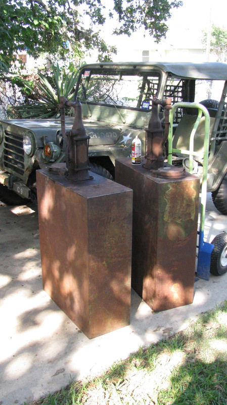
These came my way this weekend and I picked them up for a song. What I have here is a matched set of Gilbert & Barker 45 gallon bulk oil dispensers. Despite a lot of rust, some of the paint remains. The tank was green and the pump and fittings were orange.
A little history on the manufacturer - Gilbert and Barker later became more commonly known as GILBARCO around about 1935. They actually changed their company name to Gilbarco in 1965 and at present they are known as Gilbarco Veeder-Root specializing in, among other things, point-of-purchase fuel dispensers. Next time you stop for gas, have a look at the pump's manufacturer. You are probably using a Gilbarco pump.
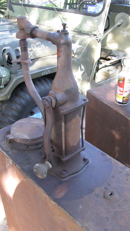
These bulk oil dispensers were in use before quart cans of oil and self-service became popular. Usually located out by the pumps for convenience, gas jockeys would place an open top oil can with a spout or a flexible tube on the large cast iron lid at the top of the tank. In doing so, they would automatically be pushing the spring loaded return spout of the tank out of the way. To fill the oil can, the jockey would crank the handle backward and forward drawing oil up from the tank thereby dispensing it, to be measured, into the oil can. When he removed it, the return spout would follow the oil can, motivated by pressure from the return spring and it would stop beneath the spigot. In this way, any oil that dripped out of the spigot would find its way back into the tank.
The large lid at the top of the tank was equipped with a removable strainer so that any oil that was unused, could be returned to the tank through the strainer where it was swept of debris. Some lids were specially cast with the name of the brand of oil. Gilbert and Barker also provided padlocks marked "G&B" which may or may not have actually been produced by another manufacturer. In any case, at day's end both the lid and the pump were secured with their own padlock to prevent theft.
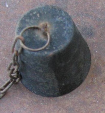
A simple dipstick was provided as a means of determining how much oil was in the tank. The dipstick enters the top of the tank through a raised area at the top of the tank. Because these tanks were very often kept outside the station they were subjected to all kinds of weather. The purpose for this raised area was to keep water from entering the tank at the dipstick hole. What is missing from these tanks is whatever cap or device that was attached to the top of the dipstick. Because no tanks that are still around seem to have that device, I'm guessing that it may have been something like a brass knob with a relieved area or escutcheon.at the bottom so as to nest over the raised area. Brass fittings always seem to be scavenged from things like this which would explain why all these seem to have disappeared with such regularity. Lubester brand tanks all appear to be equipped with a knob and escutcheon on their dipsticks. For now, what I intend to use as a substitute are several caps from tiki lamps (similar to the caps of a smudge pot). They cover the raised area perfectly. If anyone knows what these G&B caps/knobs actually look like, please, let me know.
Last edited by m3a1 on Sun Apr 15, 2018 5:26 pm; edited 1 time in total
Well, at long last I've managed to get back to this project. I did get quite a few things sand blasted and and painted. I ended up ordering a completely new hub for the left side as one of the drive flange bolts had broken off and the bolt hole was also wallowed out. Because of this I found I had only half of the bearings and races I needed today, so I got over to O-Reilly's Auto Parts just in time to get another couple of sets added to their afternoon parts run and had them in my hands in a hour. Having to step away from these jobs for a time really throws me off my game!
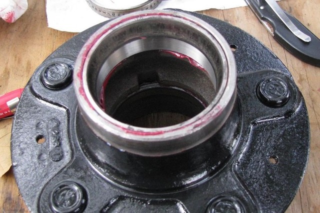
What you see here is my solution to getting the races pressed down deep into these hubs. I lubed the throat of the hub and stacked the old races (which is why I don't throw anything away until the job is done) and I used them as spacers to press the new race down until it was seated. Afterwards, I simply tapped the old bearing race out with a brass punch. If you do this, make sure the bearing races are stacked back to front so that there is a surface to strike against when it's time to tap them out. Granted, it's a little awkward-looking but I didn't have the proper tool for seating the new races and elected to use what I had on hand which is perfectly acceptable.
This is a also a good side-by-side photo of how bad the old races were, as compared to the new ones.
The front side of the hub has a relieved area all the way down to the edge of the seat for the bearing race so those old bearing races simply come right out without any effort. However, the back side is an interference fit all the way down.
Last edited by m3a1 on Sun Apr 15, 2018 5:15 pm; edited 1 time in total
Yup. I'm expecting some very good things to come out of all this drama. I will admit that I haven't gotten into the differentials (yet). Why? Well, basically because I've never actually driven this truck and as you probably already know, you can replace as much as your wallet will provide the cash for. So, I'm getting into what is most readily accessible (and what I most expect to be worn out) and thus far, I haven't been disappointed in that everything I have looked at has needed attention.
I'm happy to say I have lots of lovely bits all ready for reassembly AND I finally broke down and bought the manuals which has all the technical stuff I am really going to need for preloads and such.
Also have on hand almost every bit of the brake system I need. I'm going to take a stab at doing my own brake lines rather than paying the premium for pre-bent stuff. I have a nifty tool for making proper bends that I've been just dying to use. If you remember, my truck actually has brake line wrapped circumferentially around the axle tubes!
So here's the things I've been thinking about of late. Let us suppose that I am going to be successful in getting this truck where it needs to be, mechanically. What next....?.... because the body sure ain't nuthin' to write home about and I just don't want to have to shell out a ton of money for bringing this body back around!
At the moment, I would like very much to eventually make a wrecker out of it - just imagine an M38 adapted for use by a service station.. I have some good photos of the old Canfield wrecker kit and it doesn't look at all complicated. I'm quite sure I can fabricate something quite similar to their design. As for the overload springs, they appear to be a volute-type. And I think a good push-bumper up front might be just the thing to offset all the weight in the back.
At this point you're also probably ready to ask, Why a wrecker? Well, I think we're all in agreement that an M38 wrecker/service truck would have some very obvious limitations but the OGDI factor (Other Guys Dig It) would be pretty high, I think and having worked at a service station all through high school, it kind of strikes a chord with me.
If you have some thoughts, I'd like to hear about it.
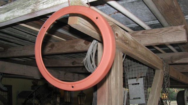
So, along the way I'm getting more odds and ends into the blast cabinet. I think I've already mentioned that there's a ton of Bondo in this truck. There was even bondo on the headlight bezels! I spent some time hammering this one out before cleaning it up. It's not perfect but it's close enough. Some of these irregularities are part of the character of the truck. I might just as easily have procured some new ones since they are inexpensive and they are the same bezels as used on most any M-series vehicle but, I just couldn't refuse the challenge.
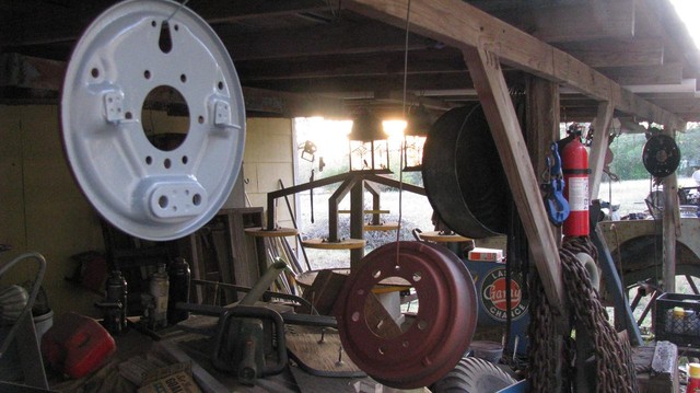
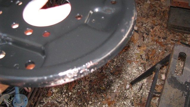
I got this backing plate all pretty and it fell off the hook and down into the gravel. (Don't ask me how, because I don't know.) Naturally, it did it while the paint was wet. I just hung it back up and let it dry and then brushed the junk off, did a light sanding on the messed up areas and then touched it up.
Well, at long last, I'm officially back at the M38. My last real efforts were back in November which is, ummm....oh SNAP!....five or six months ago!
Spent the day cleaning rust off of exposed metal surfaces of parts that had formerly been perfect. Hopefully, tomorrow I'll have the old girl back on all fours.
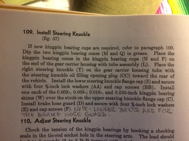
Ok, here we go! Started today with a review of my TM over coffee. Part of this image is cut off. Click on it if you want to read it. The reason I have posted this is to indicate the shim pack we'll be starting with. 30 + 10 + 5 + 3 = 48 (thousandths). Let's just call it 48 because if you're like me, when you start hearing "thousandths" your eyes start to glaze over. 48 is good enough for this discussion. In my case, I started with shims amounting to two 10s and nine 3s for a total of 47. I ordered a set of shims and they gave me a whole bunch of 3s which is perfectly OK because we will be taking away or replacing shims until we reach the desired results.
The purpose of these shims is to act as spacing. Their presence under the TOP steering knuckle flange cap (and only the top cap on the M38) creates a specific distance between the inner faces of the steering knuckle flange caps and these caps not only serve to create a fixed point upon which each kingpin bearing cone will live relative to the steering knuckle, but also exert a certain amount of pressure through those bearings and onto the bearing race which is situated on the cup at the end of the axle tube. That pressure is a farmboy's way of describing "pre-load". The fewer shims, the shorter the distance between the top and bottom steering knuckle flange caps and the result is more bearing pre-load exerted upon the bearing cones and onto the bearing race.
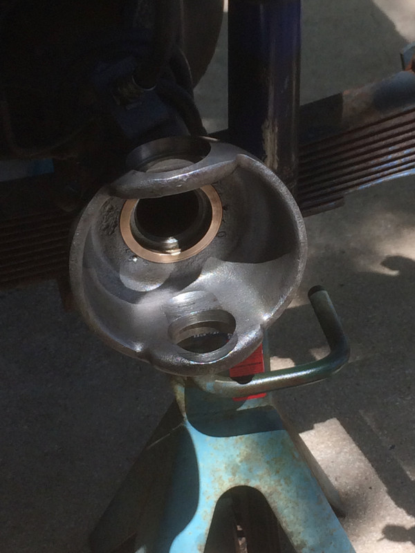
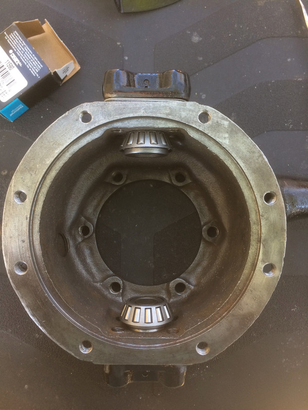
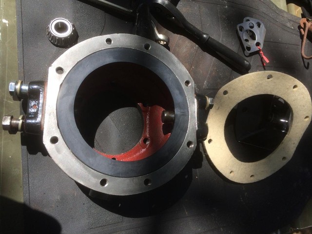
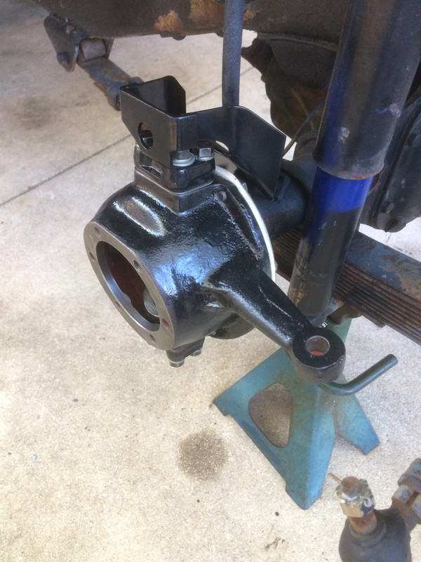
Here is the foundation we are going to be building upon today. Clean, free of debris, and about to have new bearing races installed and seated fully. Free of debris means entirely free of debris, grease, anything that takes up an appreciable amount of space. If there's junk in the bottom of the recesses for the bearing races you cannot get them fully seated and that will affect everything because we are talking about adjusting pre-load by taking out shims measured in very minute amounts (thousandths) so, take whatever time it takes to get this bit clean. This is the first big trap when renewing this part of an old Jeep. Have it clean and have those bearing races seated fully and you'll be A-OK.
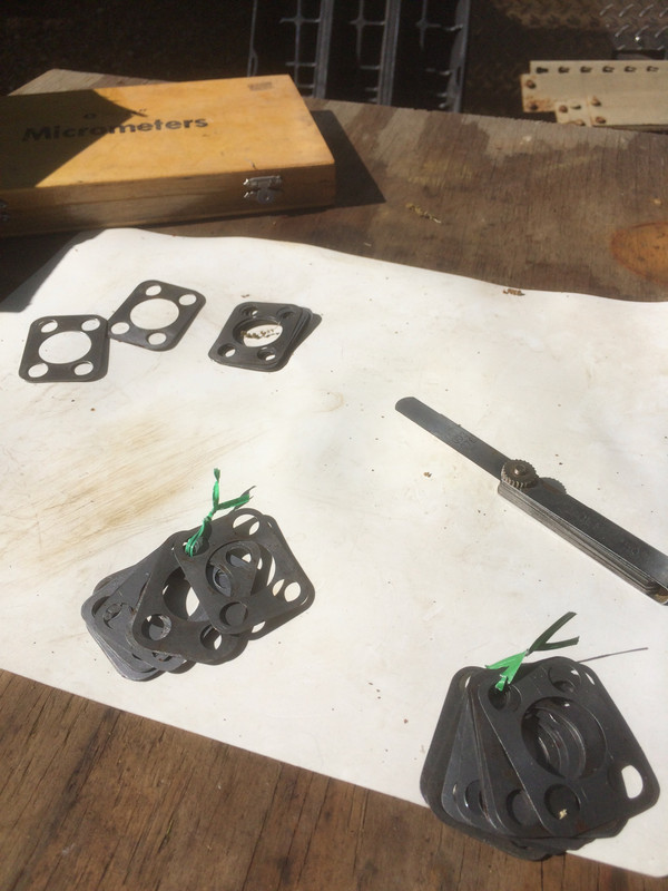
Shims, and lots of them! I started out with a micrometer then went to a feeler gauge, laying it and each shim side by side and ran a fingernail across the joint. I quickly found out most all of these were 3s. The 10s are obviously thicker and easy to spot.
When you are working with these, don't get too hung up on what is what thickness. This is not rocket science. It is the result that counts and the acceptable range for the pre-load upon the king pin bearings is very broad and ultimately, a matter of what your preference is. Our simple goal will be to end up in the acceptable range AND with equal pre-load on both sides. However, equal pre-load is not necessarily established by using the exact same number and size of shims on both sides, particularly when we are working on an older vehicle which has had who-knows-what done to it. You may recall, I've replaced a steering knuckle casting on one side so there's one possibility for variance right there.
Green twist ties tell me I have established two matching shim packs to begin working with; one for each side.
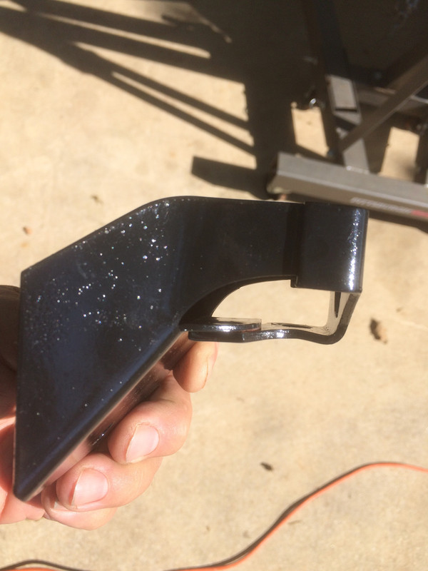
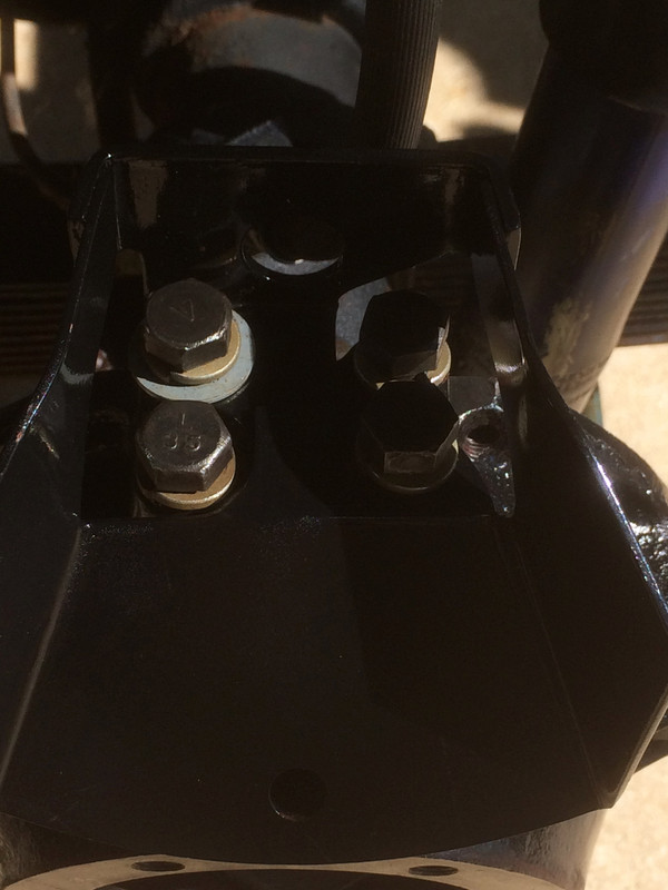
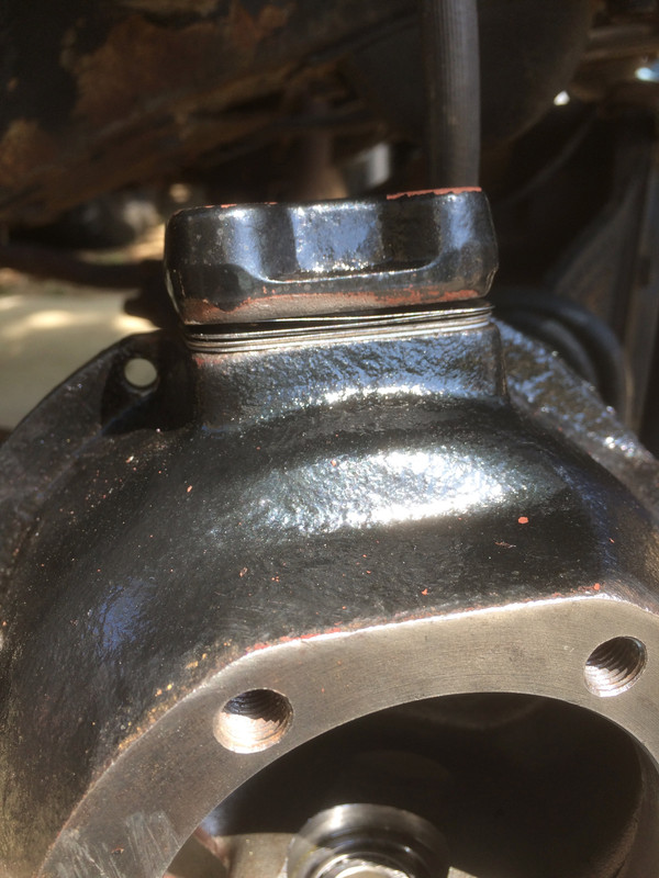
Here is the brake hose guard shown in profile. This goes on top of the top steering knuckle flange with the sloping bit toward the center of the vehicle. Only two bolts pass through this guard. I want to revisit this right now because it is VERY important. The TM is in ERROR on the matter of which bolts are used to secure this guard. You MUST use the LONGER bolts to secure it. You must NOT use the longer bolts in any other position other than the brake hose guard. If you are just coming into this here and now, read my earlier, more detailed posts on the matter. In this photo you can see that one part of the guard is almost twice as thick as the other owing to the manner of its construction. Make up the difference by putting a flat washer on the bolt holding the single-thickness side.
Take note - here you will see I have installed the hose guard 180 degrees out of phase with the way it should be! DUH! This is what happens when I'm not being paid for my time!
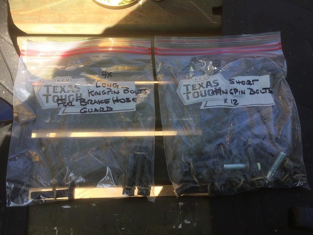
Hardware, bagged and sorted and one or two new bolts to replace those that were stretched. All of these have brand new lock-washers. New hardware is cheap. Get some!
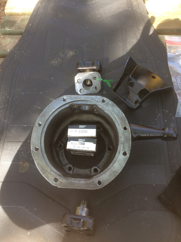
Here's the morning layout of parts in a logical fashion. Trouble is lurking in one of those 11590 bearing boxes because some nitwit returned parts and probably thought it would be cute to put a bearing race in a bearing box. Yes, I bought these from a reputable supplier whose reputation also got damaged because they didn't check it either. Finally, I got screwed when they shipped this to me (and charged me for it). So, here I am, all ready to get to work and I'm missing one @#$%&* bearing! The lesson here is a simple one. When you receive the parts you ordered, open EVERYTHING and check. Not catching this earlier is MY fault and this screw-up cost me $20 and several hours to source a replacement locally.
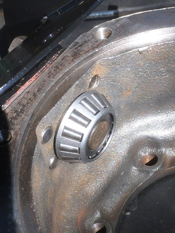
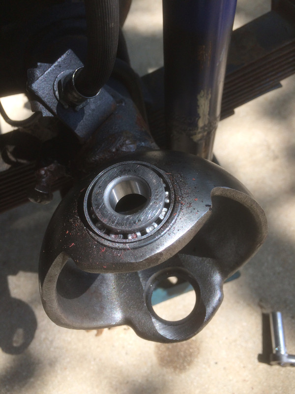
Ok, my bad. In this photo, I've got the top bearing flipped over and facing the wrong way but you should still be able to get the point. Everything you see here (and more) is suspended upon that nice shiny cup at the end of the axle tube by means of these two tiny little bearing cones and nothing more. Getting through all the banging and bashing that these vehicles endure depends upon two little conical bearings. So, the next time you're watching a video of guys enjoying their flat fender jeeps on the rocks at Moab, or an old clip of the U.S. Army guys boinking over a test track in a Jeep, think of the tremendous stresses that can be exerted upon a well-engineered (and yet very small) collection of metal parts.
Here's a shot of the top assembled without shims but without each bolt tightened down. IF everything were tightened down and IF all the bolts were in the right places and IF there were NO shims in place, you would see 1-1/2 turns of thread protruding past the inside face of the steering knuckle and guess what...a shim pack valued at 48 just happens to be about equal to 1-1/2 turns of thread. Starting to make sense?
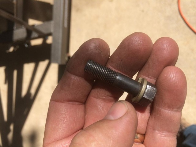
Ok, so I chased out all the bolt holes with a tap yesterday. This bolt was offering some resistance and you can see why. Trouble in the first four turns of thread and arguably as many as 13 turns. This is one of those jobs where getting the correct preload is a matter of assembling and disassembling many, many times. Having bolts and bolt holes that are true and correct is a HUGE bonus and makes a tedious job ever so much easier.
Here's a photo of shims in place with the shims oriented in such a way that I can pluck the skinny shims off with ease while we sneak up on a proper pre-load.
The matter of finding the correct number of shims to establish proper pre-load goes like this -
1. WITHOUT making any installation of the oil seals and WITHOUT packing the bearings, install your steering knuckle and it's bearings in its entirety.
2. Install the bottom steering knuckle flange caps and torque them to spec (I am using 30 lb-ft of torque and will wrap everything up with 35). The bottom steering knuckle flange will remain in place and undisturbed throughout this process.
3. Install your complete top assembly with hose guard (and that extra flat washer) and your shims. The top will be where all the adjusting takes place.
4. While you are going through the process of working out just how many shims you need to remove, tighten the top bolts down to snug, rather than to specifications. It is quicker, easier and will help speed you through the process of getting close to that optimal pre-load.
5. Make your checks for adequate pre-load, disassembling and taking away shims, then reassembling and rechecking until you are getting in the ball park. But, while you are doing this, remember that proper torque will add substantially to the final pre-load.
6. When you begin to feel your are getting close, you can start checking with properly torqued bolts.
What is adequate preload and how do we check for it? The TM calls for 6-9 pounds of pull checked at the hole for the tie-rod end. This pounds of pull is for where the steering knuckle just begins to move, not during movement. There are lots of fancy pull-scales for this purpose. I used an antique scale from the turn of the century. Whatever you use, use the same device on both sides.
Generally speaking, if you are moving a properly pre-loaded steering knuckle by hand (one that does not have its grease seals or anything else installed, you will find that it is mildly stiff and pivots with some resistance. What you do NOT want is a steering knuckle that pivots in the breeze. The mechanical advantage provided by the rest of your steering (such as the steering box and the leverage of the bell crank) balances against the resistance achieved by proper pre-load. That is why we are going to all the trouble of getting this right. It will pay huge dividends when it comes to enjoying the truck. Any prospective buyer will be seeing a lot of value when he test drives your truck and finds the steering to be smooth and responsive because as we know, these old flat fenders are notorious for having sketchy steering. Getting this job right is a bedrock principle to having good steering.
When you've determined the proper number of shims to get that steering knuckle moving with the resistance you find acceptable, remove everything and double check your bearings, ensuring there is no damage from all this fiddling around. I know what you're going to ask. What was my final total shim thickness? Well, I'm not going to tell you but is was far, far less than 48 thousandths. I watched a very reliable source on YouTube do one that required NO shims! So there can be some very substantial differences between trucks. How many attempts before I got to where I was happy with the results? Nine times on the right side where I started and eight on the left. Seems like a lot, but good prep makes it far easier.
My best advice? If you get into one of these, follow the steps until you get things the way you want them to be and so long as both sides are mildly stiff and match reasonably well. If you do that, you will have good results.
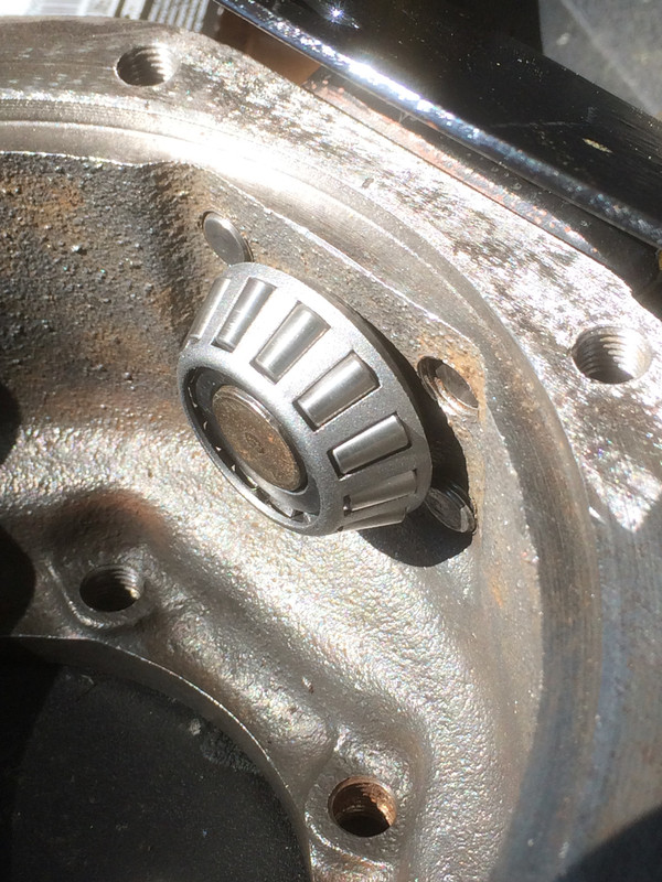
In this photo, you can see one of the reasons we don't do this job with packed bearings. See all the junk that migrated down onto it while I was futzing around with shims? Flecks of paint and whatnot, all of which need to be removed before final assembly.
Checking the new grease seal for fit. So much easier to confirm fit on the work bench rather than to having to struggle with it while it's mounted on the truck. That shiny surface needs to be painted! Since I'm waiting for another bearing to be brought up, I'll use that time to get them coated.
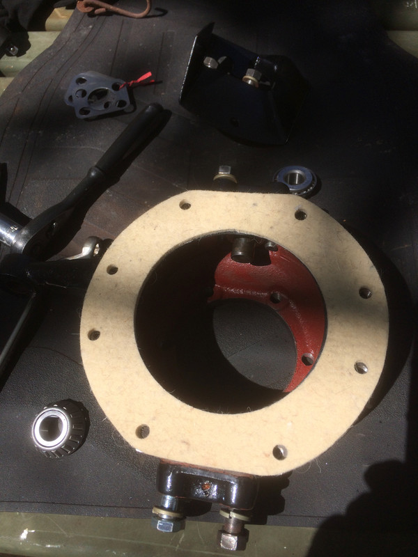
Checking the felt sweeper to ensure those bolt holes line up.
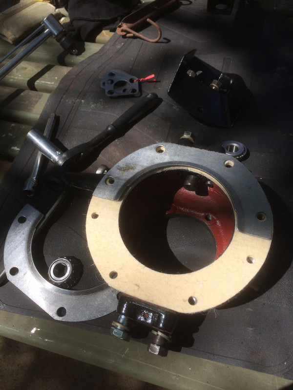
Checking the retaining plates to ensure their bolt holes line up.
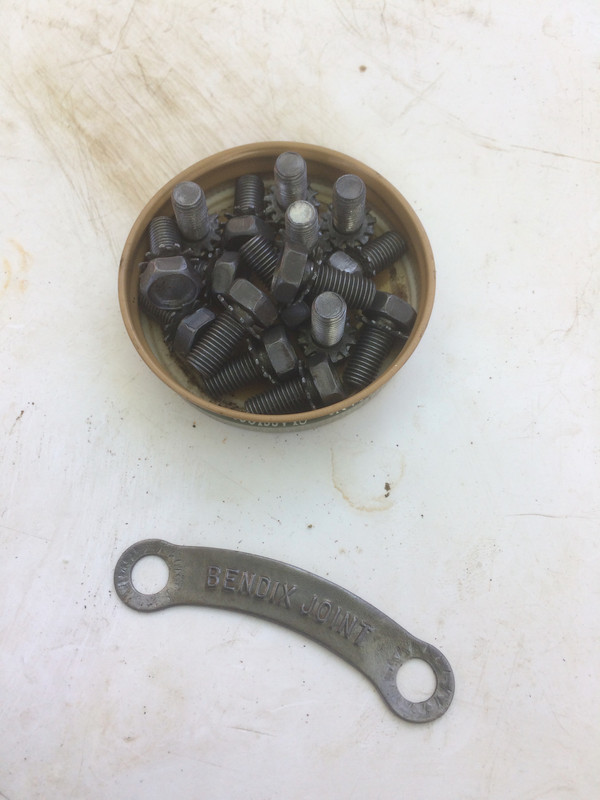
Cleaned up the original hardware for the seal kits and the identifier for the steering axle joint.
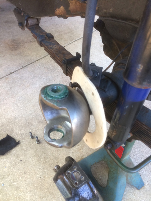
Prep for final installation. The felt sweeper goes on, over the cup and then the rubber grease seal (which is a split ring). Gentle pressure will allow you to work the split open end over the axle tube. DON'T bend it - just flex it. When the steering knuckle is in place, work the grease seal into place much as you would put a tire on a rim. Work it around until it all fits. If you took the time to fit it on the work bench this is a relatively easy task. However, if it still doesn't fit you may have to trim the ends where they meet at the split. Keep the split in the grease seal at the top, 12 o'clock position. Then, lay the felt sweeper over the rubber grease seal and the retainer over that and run your retaining bolts in, finger tight.
The felt wiper doesn't need to be oiled, though I suppose you could put some silicone on it. The bottom line is, don't put anything on your felt that will attract or hold dirt. I elected to install mine dry.
Do not over-tighten the retaining bolts for the seal retainer. Don't tighten to the point where you deform the retainer. Run them in equally. You will be able to see the threads as they protrude through the casting and in this way, judge how equal your bolts have been drawn down.
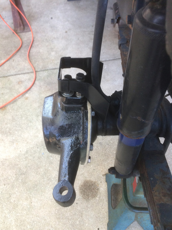
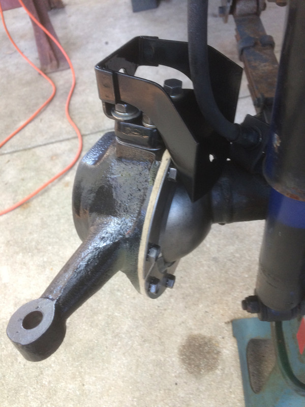
Finally, all back together (brake hose guard facing the correct direction ). You will recall that the TM instructs us to set our pre-load without the grease seal installed. Here's a problem I may be facing and a question I do not yet have an answer to. These are a new-style civilian grease seal being put to work on a very old military truck. With these new style seals installed, the energy necessary to swivel the steering knuckle is roughly 33% more than without them installed and I don't know what is "normal" for these so I intend to just roll with it as the steering knuckles are still moving in what I would characterize as the high side of the mildly stiff, rather than really stiff. But my original pre-load is right so I really have very little to worry about. Perhaps with some metal preservative (silicone) on the cup, the grease seals will start moving more easily across the surface of the cup.
Look at that glaringly white felt! I would have preferred they would have made these felt sweepers from a darker material!
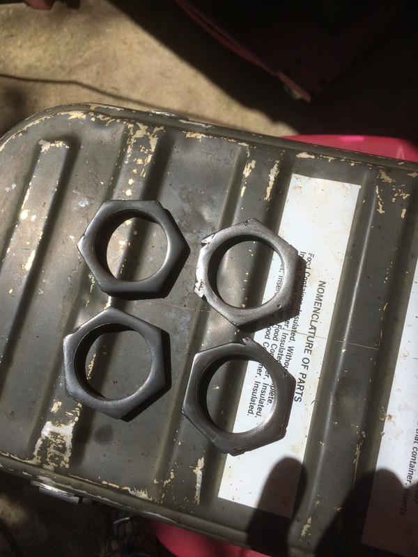
Jeep project moved forward today. I began with cleaning up some hardware. Despite the fact that I had some brand new front wheel bearing nuts on hand, I decided to reuse these since I have the correct socket for them now. I just burnished off the high points and removed the sharp edges. They're ugly but it's the center that counts. These are parts that tell some of the story of this truck and are worthy of keeping for the next guy to see.
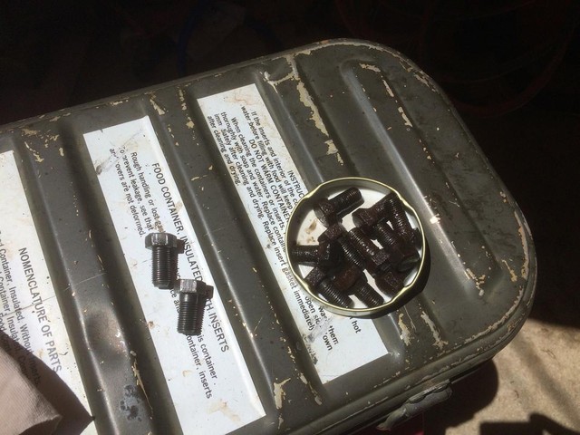
More hardware to clean up. These bolts attach the brake backing plate and the spindles to the steering knuckle. New lock washers for each one!
Since those bolts go all the way through into the cavity of the steering knuckle I installed them with Permatex thread sealant to prevent grease from migrating out into the brake area.
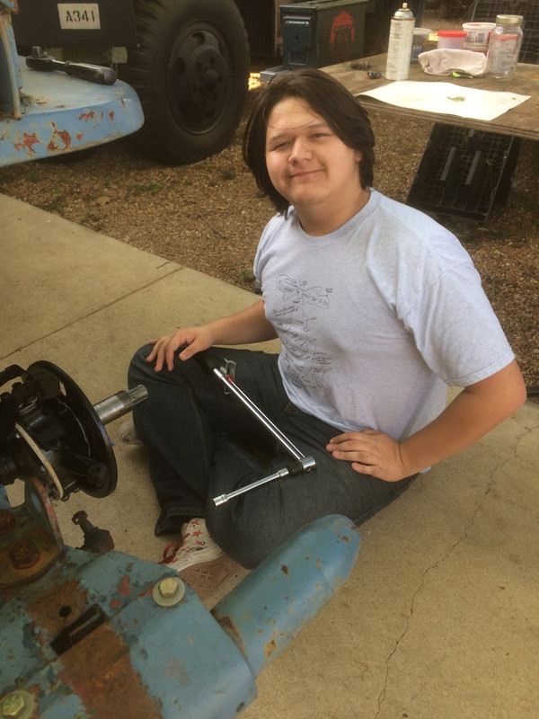
Here's the kid who, at long last, has found his way back to the project. I know....I know. He's really just a head of hair with it's own life support system.
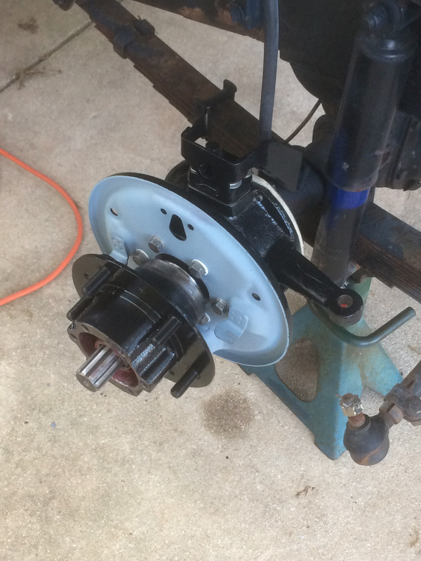
This front axle received new king pin bearings x4, new king pin bearing cups x4, one new steering knuckle, one new hub, new front wheel bearings x4 and front wheel bearing cups x4, new hub grease seals x2, new front lock washers x2 plus a whole lot of detailed cleaning and inspection. It was pretty worn out, used and abused. The previous owner had the knowin' to keep it goin' but never spent a dime on it.
Once we get this Jeep back on its wheels it will be time to address the brakes. A full brake overhaul is coming up!
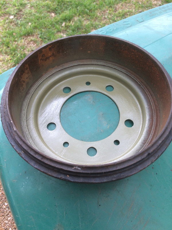
I'm so very happy to be getting this truck back on all fours! I'm unsure as to whether or not I'm going to replace these drums. There is some distortion of the deck where it mates to the hub which will likely as not flatten out when the lug nuts are tightened down. They'll all be turned of course and we'll then see where they are.
I never got around to cleaning this drum up but since it was going on temporarily, I gave the inside face a good working over and threw some paint on it.
Here, I am a VERY Happy Camper. Having the right socket for the hub is a huge bonus. I would have liked to have used this on my Bantam trailer. Alas, this socket was buried in the parts for the M38 at the time.
And then....disaster struck.....
I suppose this is all part of the process. I do my level best to miss nothing, cover all the bases, work methodically and efficiently....and then I drop the ball. So the only thing left to do is try to deal with the problem with a modicum of grace and humility.
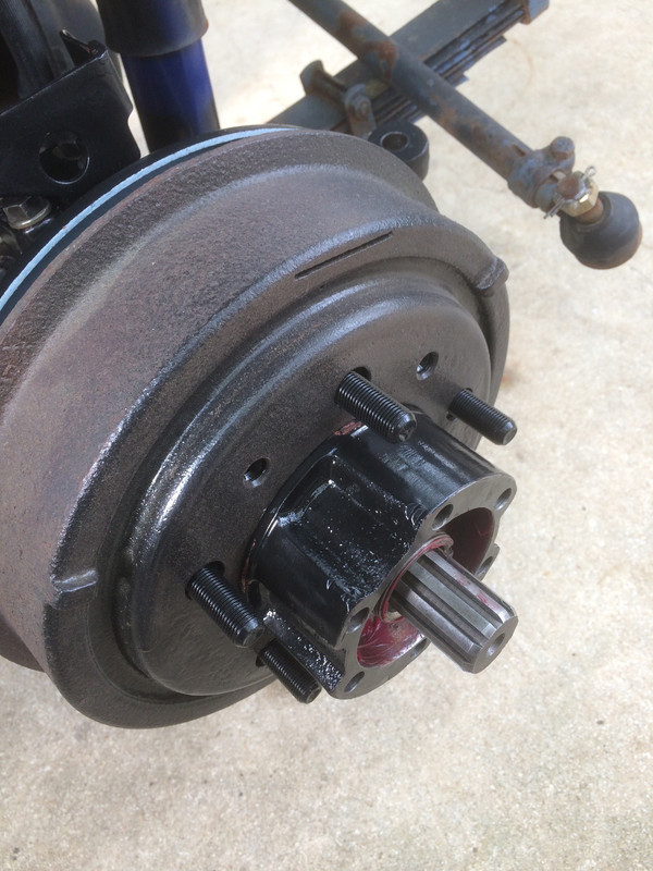
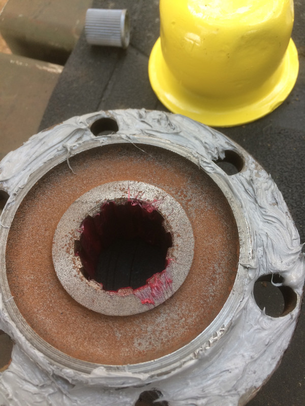
ONE of these bolt holes got overlooked. I cleaned these up by hand, carefully cleaning out each bolt hole and running a tap down into it but, as it turns out, somehow I missed one and, as luck would have it the one I missed is totally fouled up. Had I found this earlier I would have replaced the hub altogether, just as I did on the left side. Maybe I did find it and then forgot to order a replacement. Heck, I don't remember. But what to do now? Well, it's a little cheaper to heli-coil this and (lucky you!) when the kit comes in, you'll get to see me put one in. I wouldn't mine spending the money but remember, there is still the expense of a full brake overhaul ahead of me.
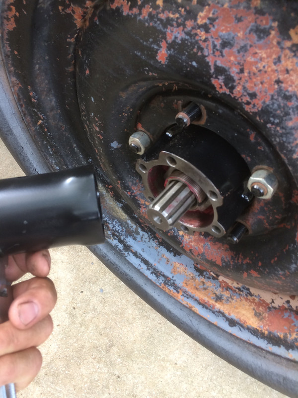
But, when this picture was taken, I was still oblivious to the problem; the mating surfaces are getting cleaned up with acetone and I'll be getting that lock washer bent over. By the way, getting the lock washer bent over is best accomplished by putting a small starter bend in the edge of the lock washer before installing it. Also, the tab of the lock washer (which goes in the keyway) points inward when being installed.
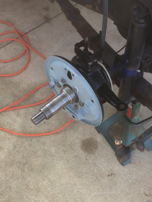
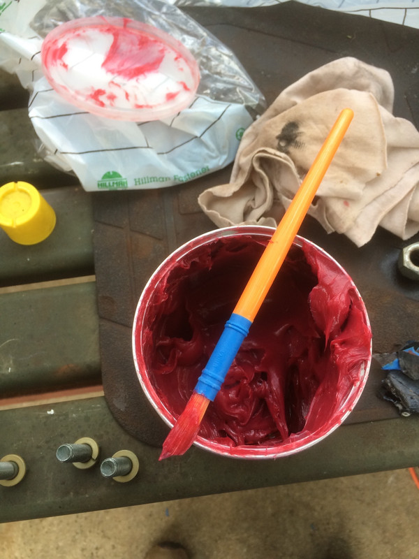
With one of the many small disposable brushes I keep around for jobs like this, the splines of the axle get lubed...
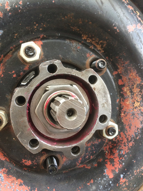
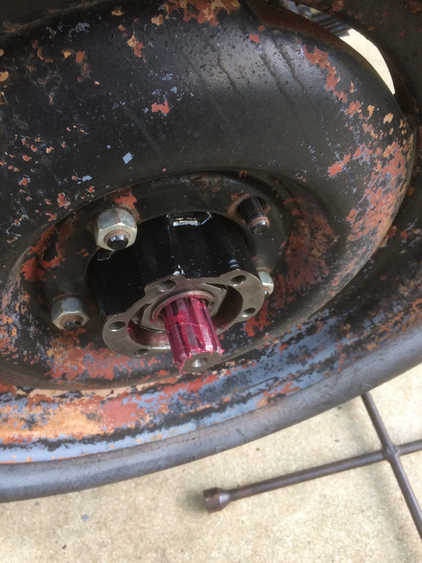
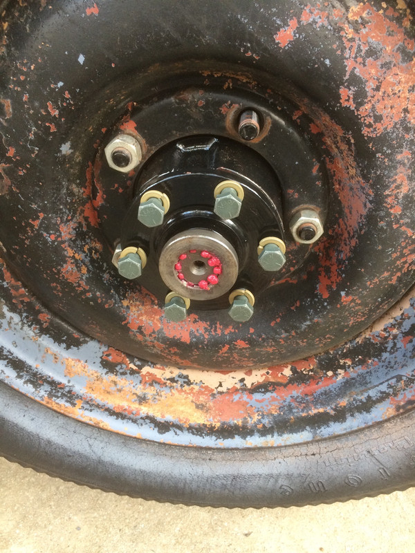
...as do the splines of the drive flange. The flange gets a coat of RTV (gray, non-rigid). With RTV, using a paper gasket is unnecessary. Don't get too hung up on that flash-rust in the middle. When that gets coated with grease, that'll end that rust's progress very quickly. Why didn't I clean it up (as I normally would have)? Well, there was some weather coming in as I was putting this all together and I was running out of time.
And with new hardware all ready to be drawn down, this is where I discover the problem with the bolt hole. DOGGONE IT! So, I snugged the five good ones down but no so tight as to squeeze out all the RTV, thereby making a good gasket. These will be torqued down equally once I have the last bolt hole sorted out . So, I have a $&%-coil kit ordered from Summit Racing, plus the "special" drill bit of 25/64".
I just HAD to throw this photo in. And you think YOU have problems with oil leaks! Dig the crazy catch basins below those big radial engines. Owners of all types of former military vehicles seem to have the same problems.
I came across this while on a mission yesterday. It's an A-26C Douglas Invader (tail number N4818E) and it's the "hero" aircraft used in the 1989 movie, Always (Dreyfus, Hunter, Johnson, Goodman). It's tail has since been repainted and it has actually been converted to a tanker for fighting fires and was in this configuration during filming. Having an A-26 is on my bucket list. SO COOL!
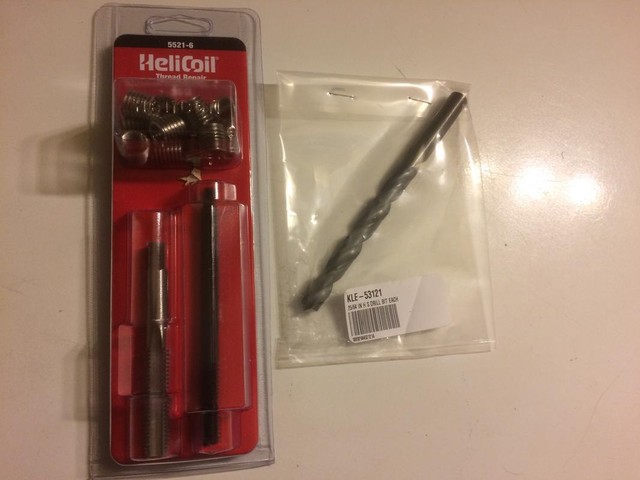
Got caught up in a little work so haven't been back at the Willys yet, but Summit Racing delivered my Heli-coil kit in two days ($20.99 for the Heli-coil kit).
This kit comes with 8 coils which are the consumable bits. So, I can repair not only the hub that I'm using on the Jeep but I will ALSO sort out the other hub that I initially replaced on the left side. I suppose I could recoup most all of my purchase if I really cleaned up the other hub, fixed the botched bolt hole on that one and offered it on eBay and it would be a very substantial savings for someone; far cheaper than having to bear the cost of a new one (at $67). Sell it or keep it as a spare, I really have no down side here.
Some of you already know about Heli-coil threaded bushings and some of you may not so, here's the skinny..
I have a messed up bolt hole that is supposed to be 3/8" x 16 turns (coarse thread).
So, the procedure is to drill out that hole with a 25/64" drill bit which is 1/64" OVER 3/8" (and if you want to do the math, 3/8" equals 24/64").
With that done, I'll re-tap that hole with the tap they've provided which is the correct size for the little wire coils in the kit.
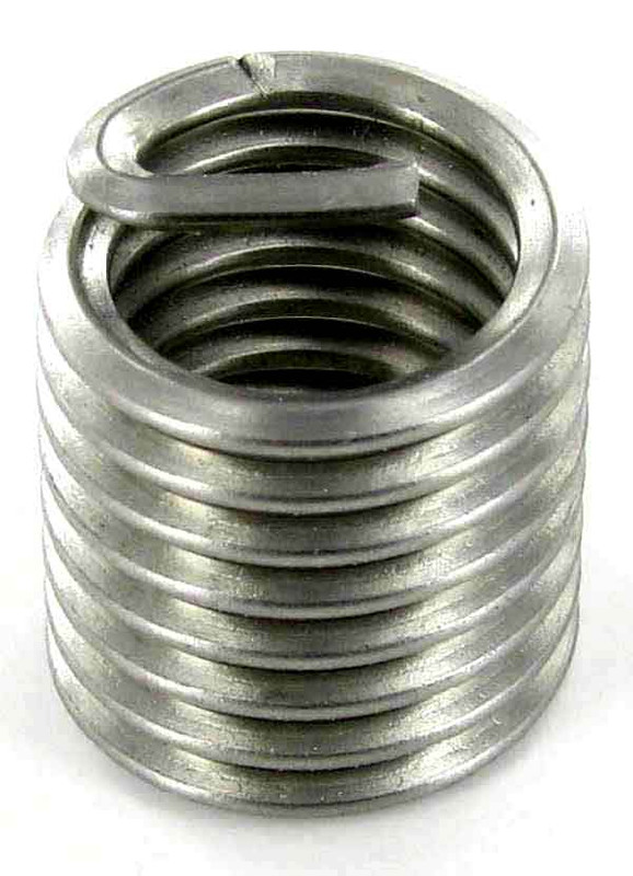
With the coil screwed into place, the interior of that coil provides the correct dimensions for the original bolt size (3/8" x 16 turns).
Here's the clever bit. Each coil's wire is turned over at one end and that turned-over bit (the tang) is what the installation tool uses to motivate the coil to turn while it is being screwed into place. Once the coil is screwed in to the appropriate depth, you simply take a punch, insert it and strike the wire bit which is scored in such a way that the little wire snaps off permitting a bolt to thread fully through the coil. Obviously, you'd first need to remove the tang once it's snapped off.
Ingenious, eh?
The downside is that once installed, each of these coils provides only about 7 full turns of thread but for the hub flange which is held on by six bolts (which is gross overkill) I can live with it. If I was working on a performance vehicle I'd be sourcing taller inserts with more turns.
Here's a link if you're interested in reading more about the installation process.
You cannot post new topics in this forum You cannot reply to topics in this forum You cannot edit your posts in this forum You cannot delete your posts in this forum You cannot vote in polls in this forum