Hooray! Got the old Willys back on all fours today. Several days of people demanding my time kept me from it.
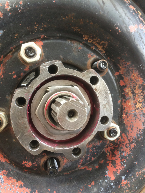
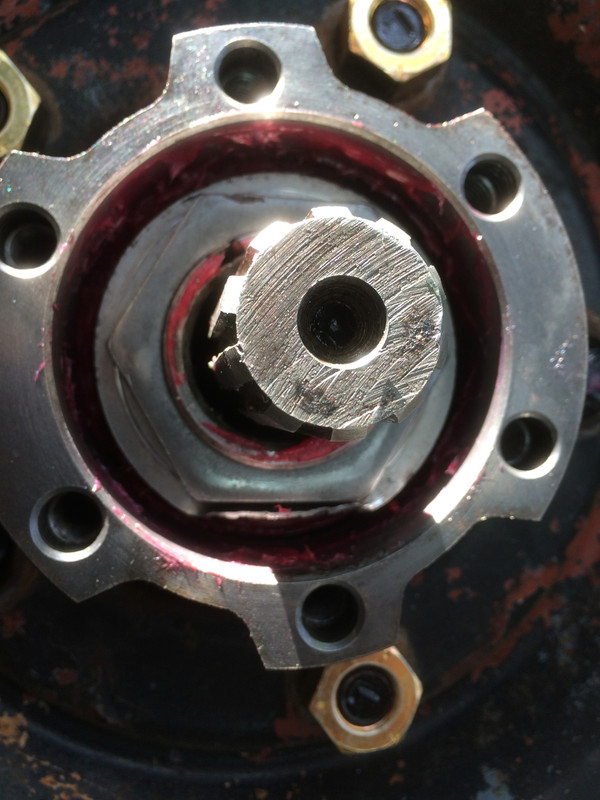
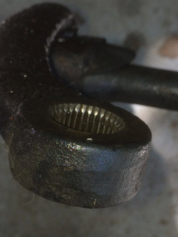
So, I found that I had a bolt hole that was FUBAR and this required a heli-coil insert to sort it out. This meant that I had to remove the freshly installed hub drive flange in order to sort it out but I left the hub on the truck. Taking it all the way off just for this seems completely unnecessary.
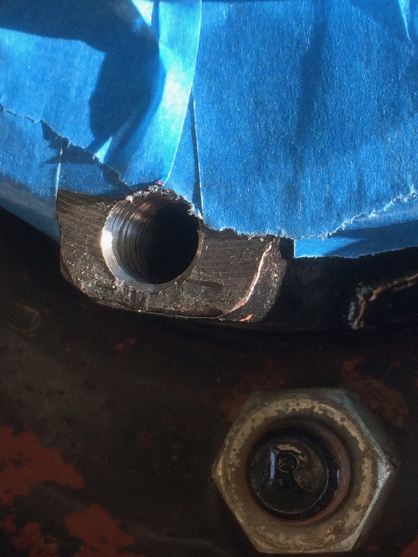
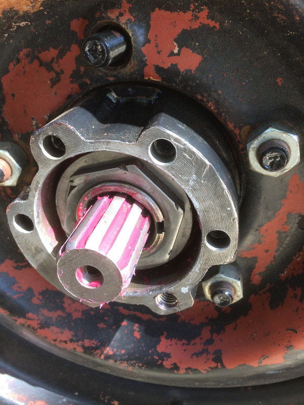
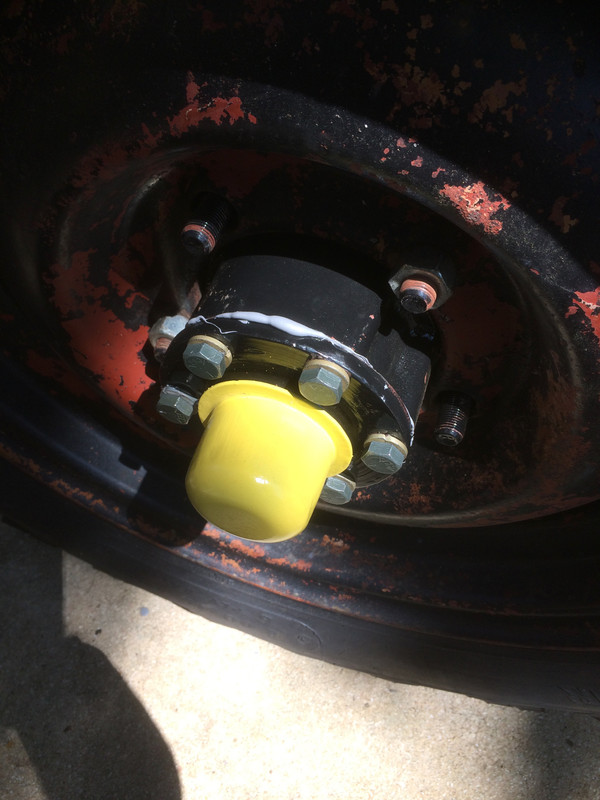
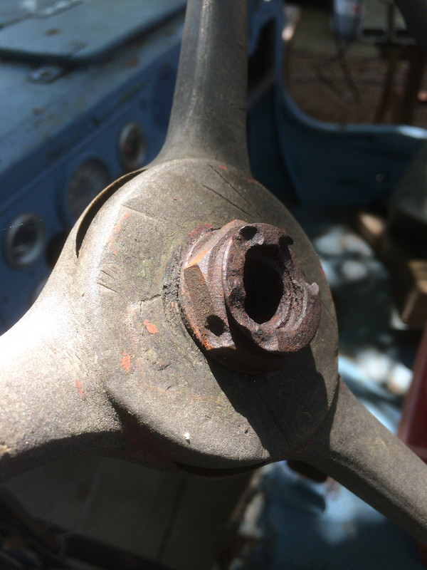
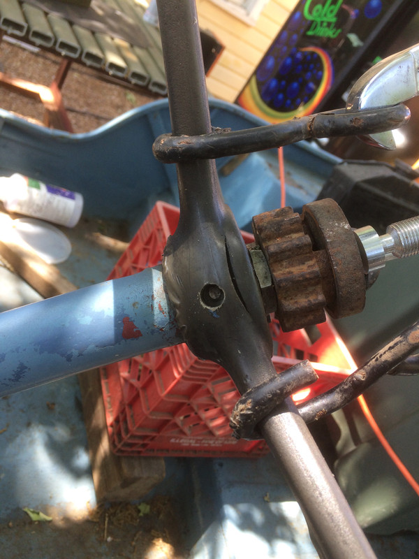
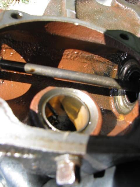
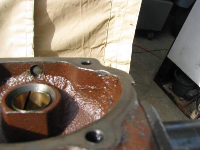
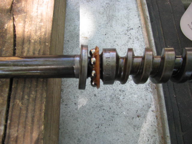
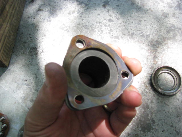
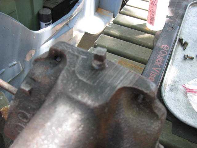
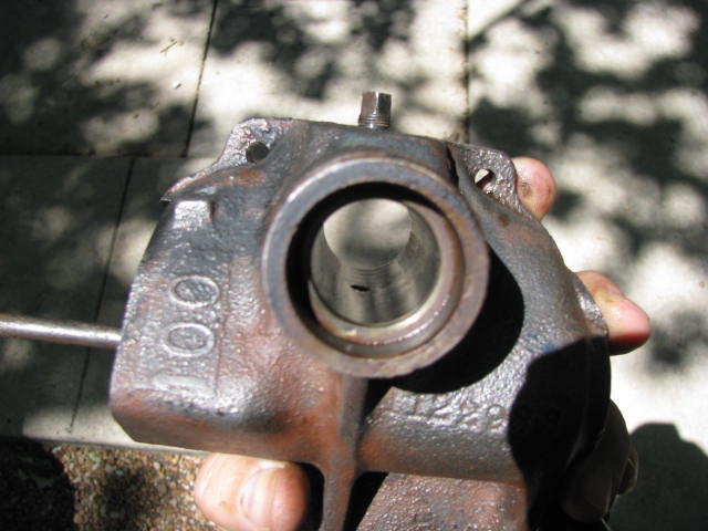
Can you identify the bolt hole that needs attention? You guessed it....at the 11 o-clock position in this photo. The original left hub also had a bad bolt hole (and you have to ask, why does something this easy get screwed up with such amazing frequency?) but it was rather wallowed out so it still may not be repairable.
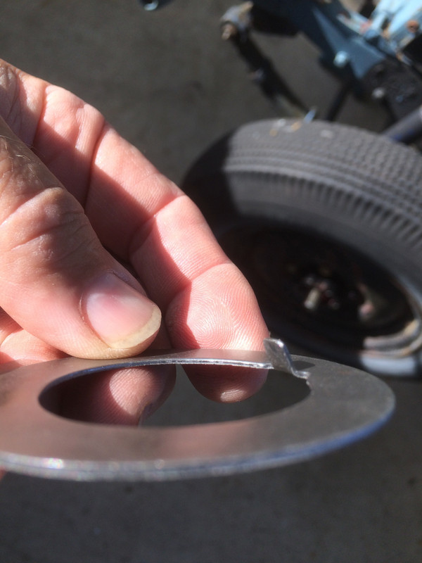
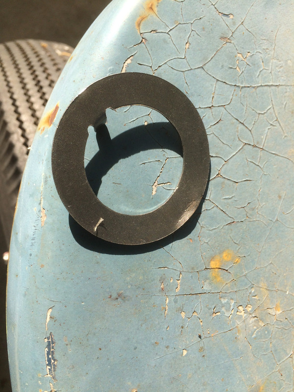
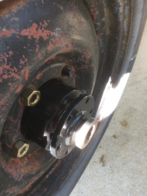
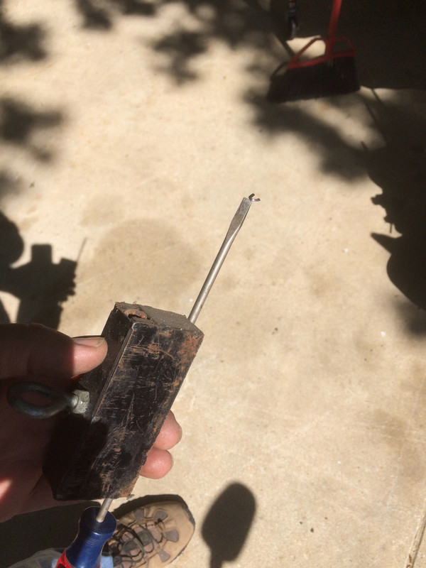
But first, I need to install the left hub's drive flange and get that side wrapped up. Here we have that hub's lock washer. Notice the tab sticking up? That rides in the keyway of the spindle and on installation, the tab points inward toward the centerline of the vehicle.
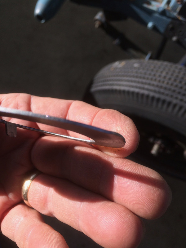
The purpose of the lock washer is to secure the outer jamb nut and keep it from backing off while it's hidden away down in there. This lock washer gets bent over against the nut and that's all there is to it. It can be reused several times but after a while, it'll be time for a new one. The hard part is getting the bend started and it can be tricky chiefly because it is situated rather deep within the hub. The solution is to start just a small bend before installation. Just pick a spot and put a very modest bend in it. In doing so, the little bend create a place to get a flathead screwdriver behind it. Just remember - Keyway tab goes inward...little bend goes outward.
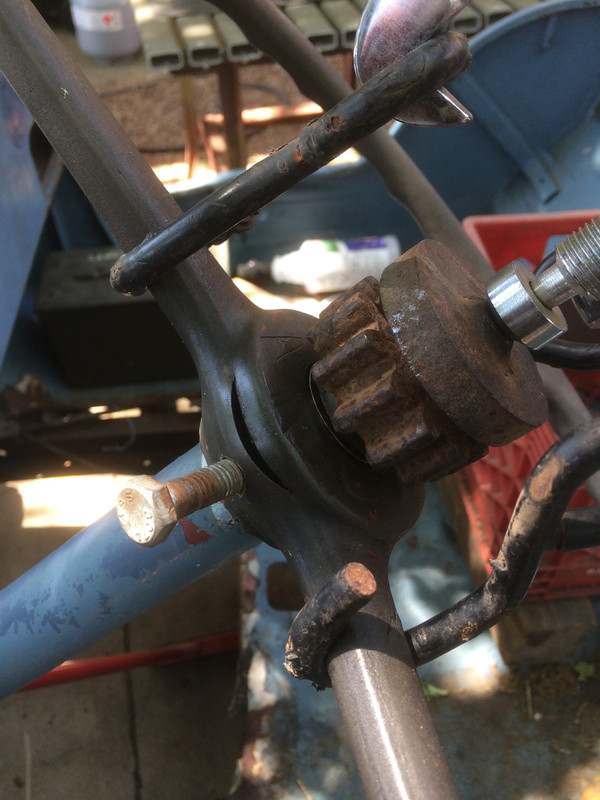
Judging from this photo, my bends are gross overkill.
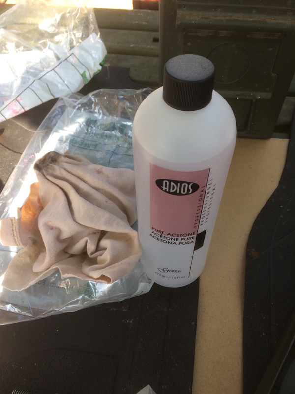
Acetone makes a great chemical for cleaning up those surfaces that are getting RTV put on them. Any other time I run out, I'd get a big ol can of this stuff at Home Depot but I happened to be at the grocery store and Acetone just happens to also be used as nail polish remover, so adios oil, dirt and grime!
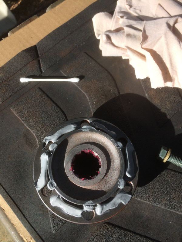
RTV made for gear oil was my selection for sealing this and I'll spread it around with the Q-Tip but beware if you use a Q-Tip because by the time I'm done spreading this stuff around, there will be a tail of cotton hanging off the swab and that is something you really don't want in your RTV seal. a Q-Tip is clearly not the best choice for the job but it was the closest thing at hand.
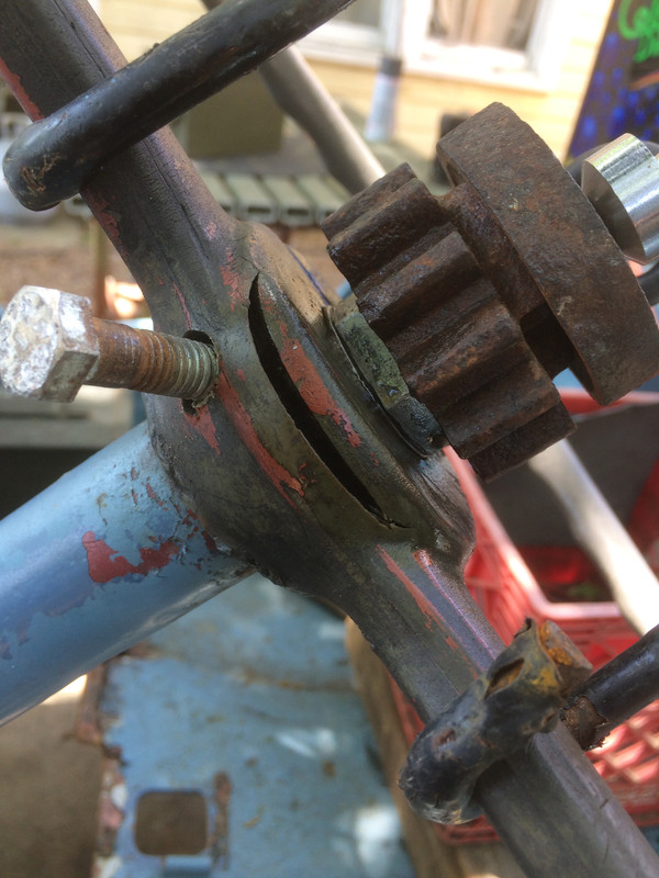
This is what your RTV seal looks like after you just barely tighten the bolts down on the hub drive flange. Do that, let it cure and then come back later and torque things down to your satisfaction. That's a pretty good looking seal. All the little irregularities in the face of the mating surfaces have RTV in them. Some RTV will squirt out when you first put the hub drive flange on. Let it cure (if you can afford to leave it alone for awhile) and then peel off the overflow.
Well, I'll be darned! The holes don't line up! (just kidding) The truck is up on jack stands and I'll just rotate the hub and wheel a few degrees until the holes do line up. If you rotate the drive flange you'll be moving the axle and the gears and all the little bits inside.
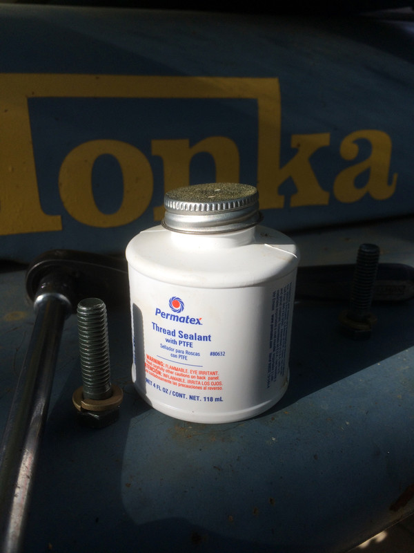
This stuff is fabulous. Out of the jar, it's the exact opposite of Permatex Aviation sealer. It's thick, white and clingy instead of thin, black and sticky. When it cures it becomes very rubbery. Permatex makes good products. However, in the business of putting everything together, I would like to suggest that you dope up one bolt at a time, just before you put each bolt in rather than coat all the bolts and then start putting them in....just in case you run into trouble. In this way, if something does go wrong you'll have fewer bolts to wipe down. This sealer creates a very good bond to the bolts and believe me, it isn't something you want to have to wipe off.
Do these bolts need to be sealed? After all, the bolt holes are blind (closed off). Well, I've seen hub drive flanges leak and I've seen that leakage migrate into the retaining bolt holes making an awful mess so I'm sealing mine so the next fellow doesn't have to go through all this again.
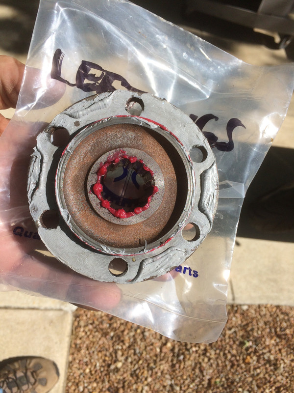
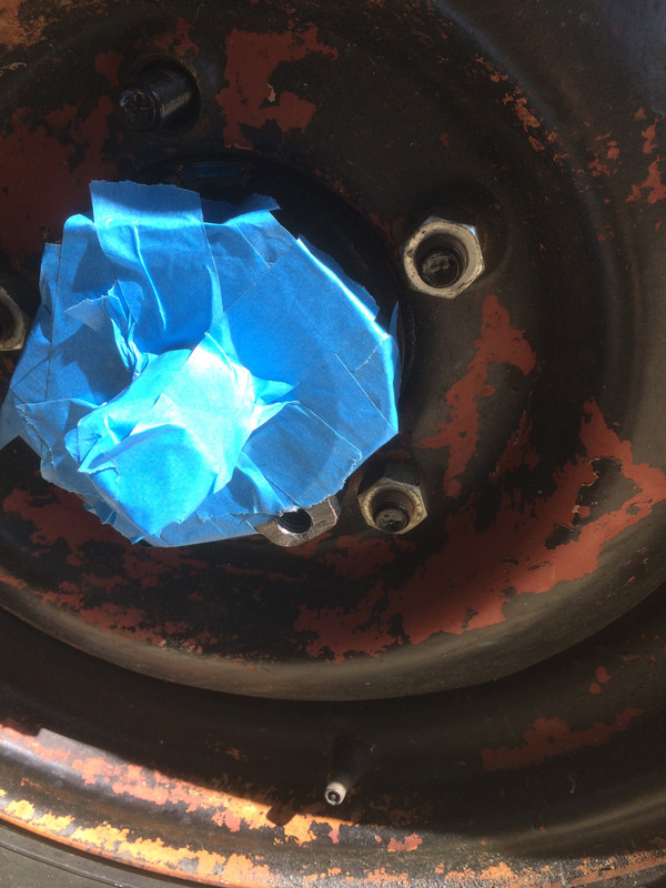
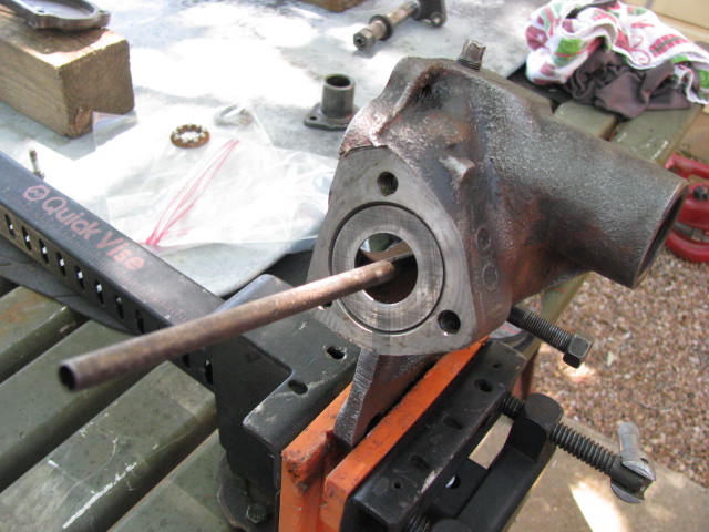
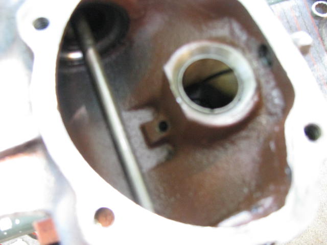
Ok, I've got the left flange installed and now it's time to sort out the right side. In preparation for installing the heli-coil, I've removed the right hub drive flange and masked off the places where I really don't want little metal shavings to end up.
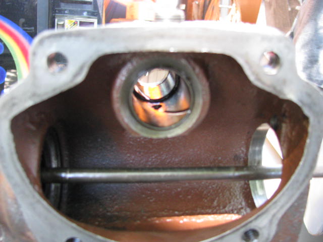
Here are the results from drilling the hole out to 25/64 and tapping the hole with the special tap provided in the Heli-coil kit. By the way, this is a special tap created especially for the Heli-coil and is not interchangeable with other, regular taps. So, if you use one of these, when you're done, keep it separated from other taps!
25/64 is just barely larger than the original hole and I found the drilling to be especially easy because the drill is taking out only what is left of the original threads plus just a tiny bit more. In the business of drilling this out, I discovered why this bolt hole was all screwed up. As it turns out, an earlier bolt had broken off deep in the hole. Someone center-drilled it but couldn't get it out with an easy-out and so, abandoned it in there and yes, it was still in there! Anyway, they switched to a shorter bolt but apparently that bolt was just a bit too long and when they tightened it down against the remnants of the first bolt, it stripped the threads. Happily, I was able to drill out the whole thing and start with a clean, fresh hole to full depth.
After tapping the new hole to full depth (which also went easily) I blew out the hole with a breath and (pay attention) the following is the most important thing I have to say in this posting. USE COMPRESSED AIR because a puff from your mouth simply ain't going to cut it. When I switched to my air hose a ton of shavings came out. Yikes! Glad I did that!
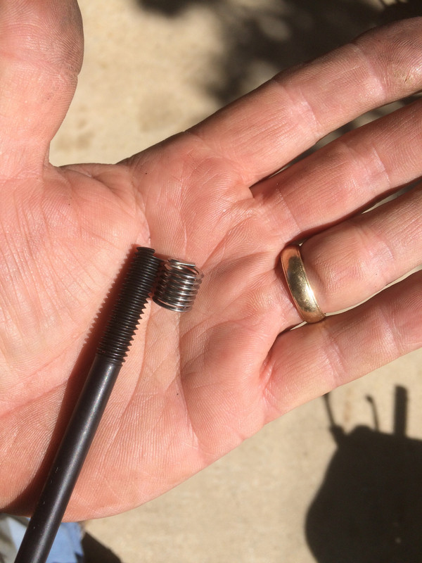
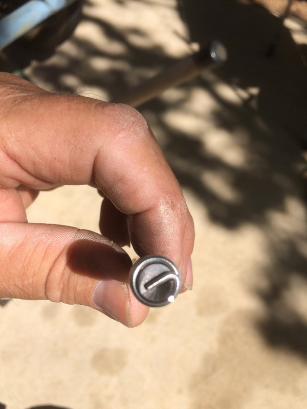
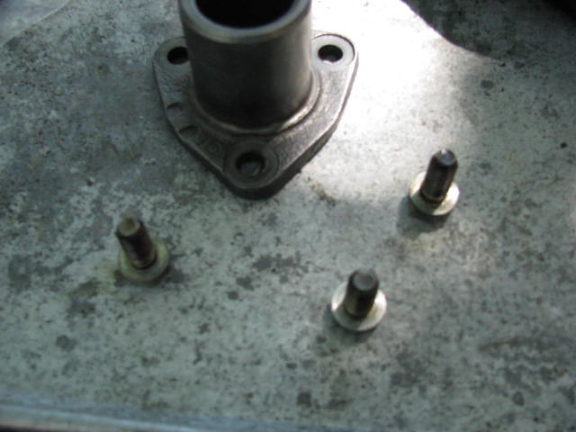
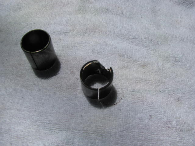
Here's the heli-coil and the driver.
Here's the heli-coil ON the driver and you can see how the driver engages the coil; far different from earlier kits that use a rod with a slot in it.
Looking at this you can see why it's important to have your freshly tapped hole clean, dry and free of all debris. It almost looks like jewelry. Heck, I may give a set of these to my wife for Christmas and tell her they're earrings!
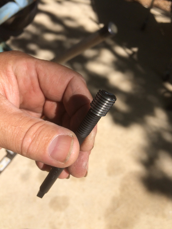
And here is the heli-coil installed. As recommended, 1-1/2 turns below the face of the hub. I put four little dots of red (high strength) thread-locker on the outside of the coil as I screwed it in. It penetrated the coil and it also ended up on my driving tool. Having thread-locker on the inside face of the coil is something we don't want, so, I swabbed the inside of the coil with a dry Q-Tip and then cleaned off the driver with acetone. I did not stack the coils as I might have and if I had I would have achieved far more turns for the bolt to grab on to. I was satisfied with one coil because as I said, having six bolts on this flange is far more than is really needed, particularly at this stage of this truck's life.
I reached inside the installed coil with some long needle-nose pliers, grabbed the tang and pushed inwards sharply. Off came the tang, just as designed, but I dropped it. So, I got a big magnet, put it on my long screwdriver and retrieved the tang. I might just as easily have used compressed air to get it out but in doing so, I would have lost track of the tang and then wouldn't be sure I had gotten it out.
And, everything went back together smoothly, just as it should have in the first place. I did use a grade 3 lock washer on the bolt in the heli-coiled hole (all the rest are grade 5) so as to ensure that I know which hole is heli-coiled in the future.
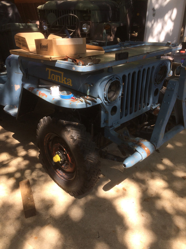
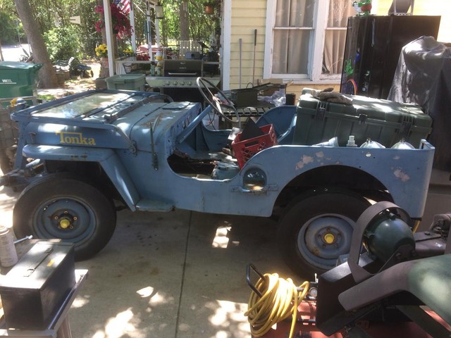
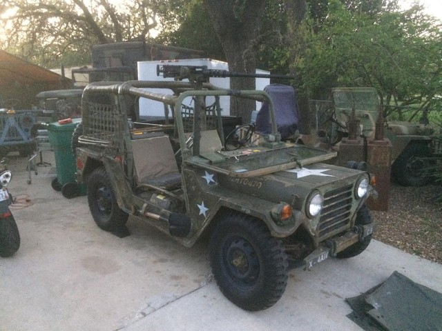
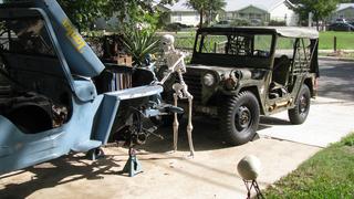
At long last! Back on its wheels!!! Like my yellow hubcaps? Obviously, we don't take anything too seriously around here.
I thought this photo of my son is appropriate. So long ago I brought my first GPW home and then took it apart; something my young son was clearly NOT happy about! I figure I owe him at least ONE jeep and today, we are just a little bit closer.
Cheers,
TJ
Last edited by m3a1 on Tue Apr 24, 2018 8:26 am; edited 2 times in total
I took some time to catch my breath on this project and did a layout of all my new brake parts and a few little housekeeping chores on the MUTT.
New brake lines throughout were always part of the plan for the M38 and I didn't have those yet. I was considering making up my own and while I have the wherewithal, I just don't have the inclination so I found a pretty good deal on an OMIX kit on the internet (and "free shipping" is often the deciding factor, right?). So, those are on the way.
For the old hands, this is going to be a rehash of a time-worn topic but for you new readers who are here looking for inspiration, brakes and being able to stop should be a pretty high on your list of things to do. I admit I wasn't always so circumspect about such things but over the years I have developed a certain methodology to these projects and it usually starts like this -
1. The project needs to be mobile, chiefly owing to the lack of space I have around here and the obvious convenience of it. So, in the beginning I focus on axles, meaning things like bearings and bearing cups and tires (no matter what their condition) that actually hold air, which does not include tires that need to be aired up every five minutes. Anything that can make my project into a smooth roller is number one on my list of things to do. Suspension can usually wait unless it's a serious problem, otherwise I let that go till later unless it's convenient to address it. By way of example, if I have an axle off the truck, it would be an excellent time to deal with whatever was holding that axle in place, right?
2. Then, I like to work on brakes because even if you're not necessarily having to work on those axles, you're going to be down there snooping around. Brakes are really a good place to put your money. Not only is it important to you that your vehicle be able to stop, especially since it's going to be you behind the wheel, but it is also a place where you can see a return on your money no matter where you are on your build. By that, I mean if you get in a bind and have to sell your beloved project (and there is no dishonor in it because we have all been to see that particular elephant) having a solid brake system on it can be a huge selling point.
Beyond all that, you can go in whatever direction makes the most sense depending upon the condition of your vehicle.
Here it is, Sunday morning and everyone kept late hours last night except for me so I'm up and have to keep quiet while everyone else sleeps.
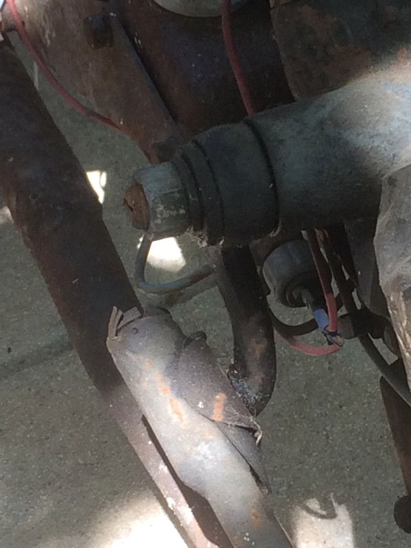
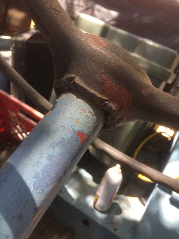
Made a cup of coffee and went out to look over the Willys. We are waiting for brake parts and while I'm not yet ready to go off in another direction on this project, I decided I had better have a closer look at the steering which we haven't gotten into in-depth yet but I DO know it's really sloppy.
There is a lot of slop in the steering but closer inspection reveals that minimal input on the steering wheel develops an almost immediate reaction from the sector shaft which can be detected at the nut that secures the pitman arm. I also noticed when the slop ran out and things began to move the pitman arm was kicking out (deflecting, rather than transmitting that energy straight to the drag link.)
One might also describe the pitman arm's initial movement as wobbling. Having a pitman arm that isn't solidly attached to the sector shaft is a HUGE no-no on any vehicle.
There was a time when part of my duties was a being DOT inspector and a pitman arm that did that would put a truck out of service. Imagine sharing the road with an 80,000 lb truck with bad steering.
This is something that should not be fixed by welding the two parts together though there are those who would attempt that. It is far simpler and safer to take a deep breath, pull it out, take it apart and fix it correctly.
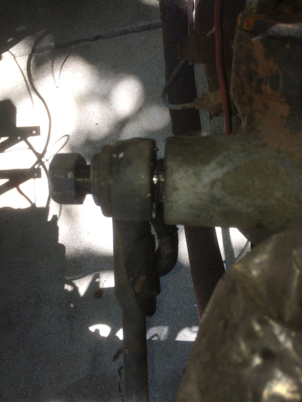
So, I loosened the nut and eased the pitman arm off by putting a small screw driver behind it. Sloppy as it was, the pitman arm came right off.
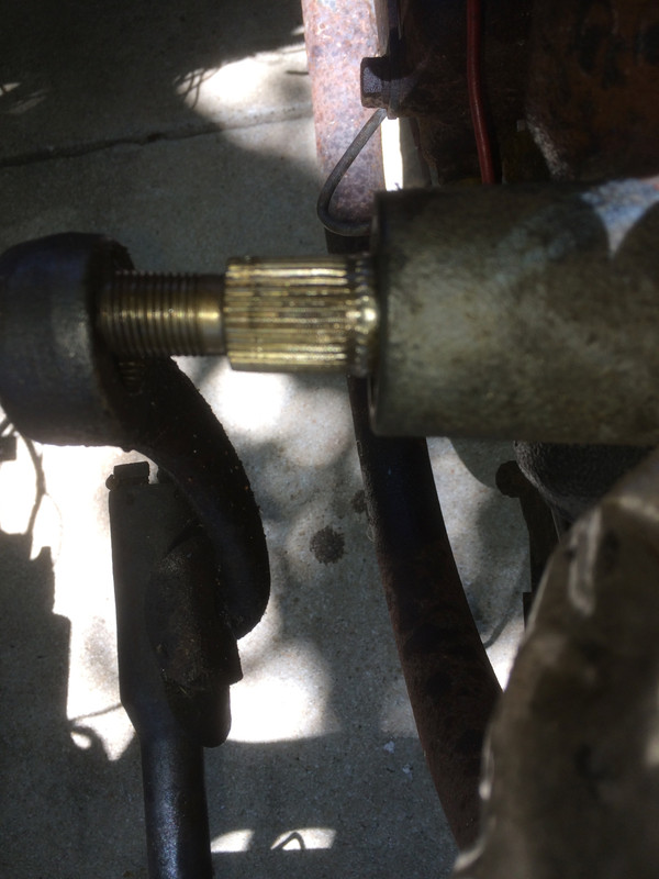
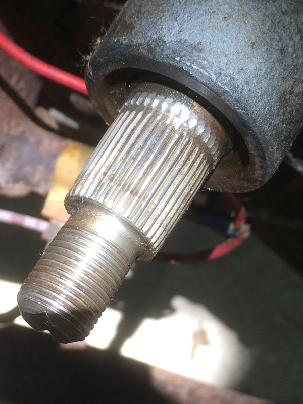
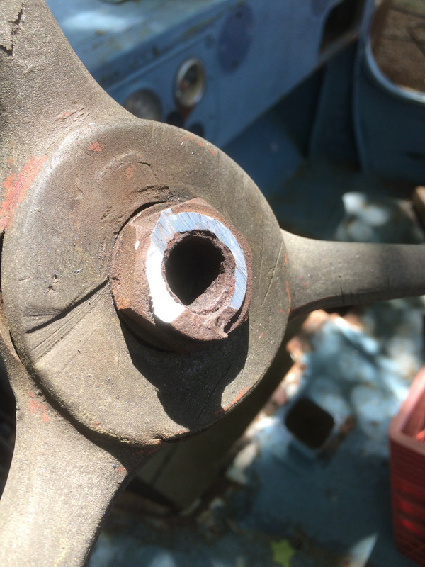
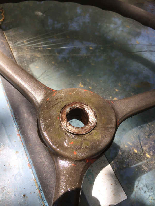
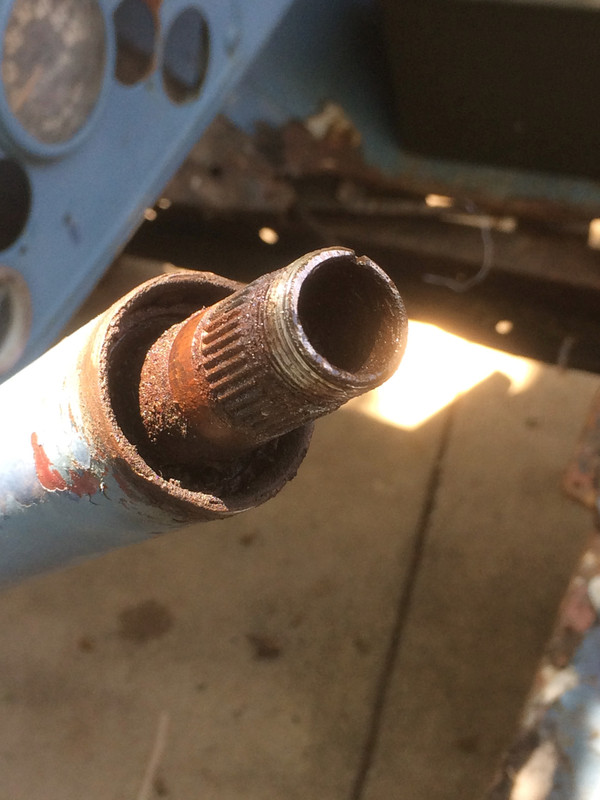
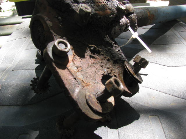
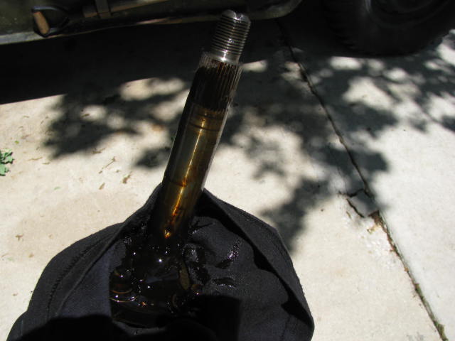
Cleaned up the splines to have a better look. I know. Not the best focus.
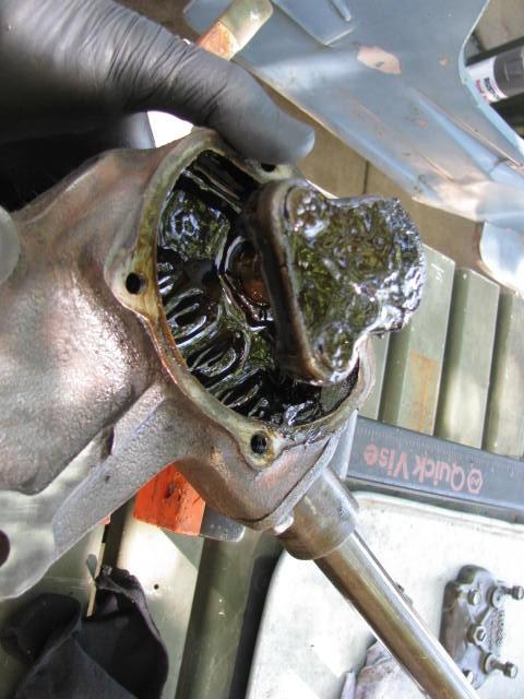
Here we find quite a bit of gunk built up on the side of the pitman arm which is an indicator of a potential leak at the steering box, but who really knows at this point. It really has nothing to do with the wobbling but it is something I'll keep in mind.
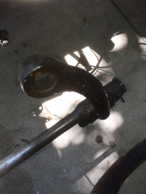
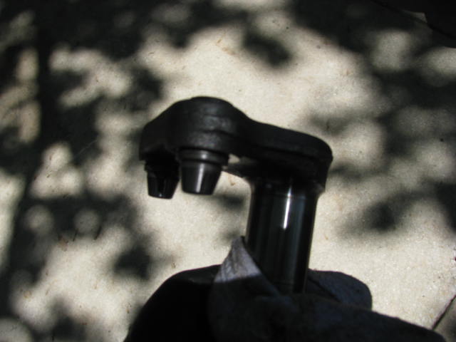
I don't know what is "normal" but I don't like the look of those splines out at the end.
Furthermore, those splines should be cut nice and straight. If you look carefully you'll see they're rather belled out (high in the middle and low on the ends) which is no surprise. That, right there, is what is allowing that pitman arm to kick out.
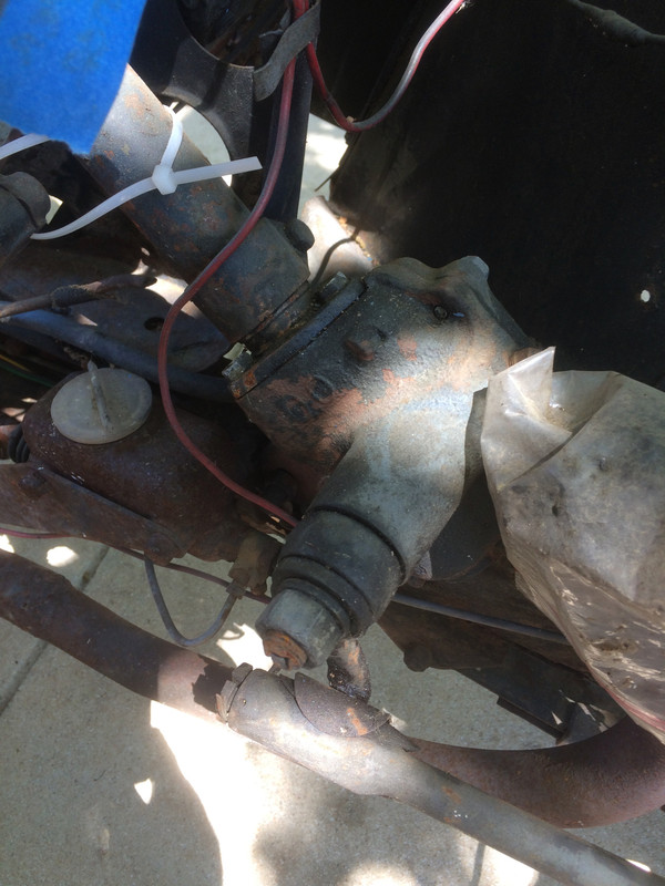
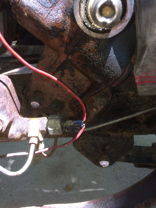
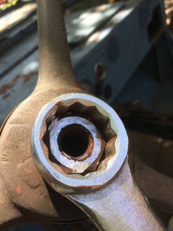
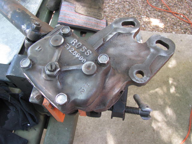
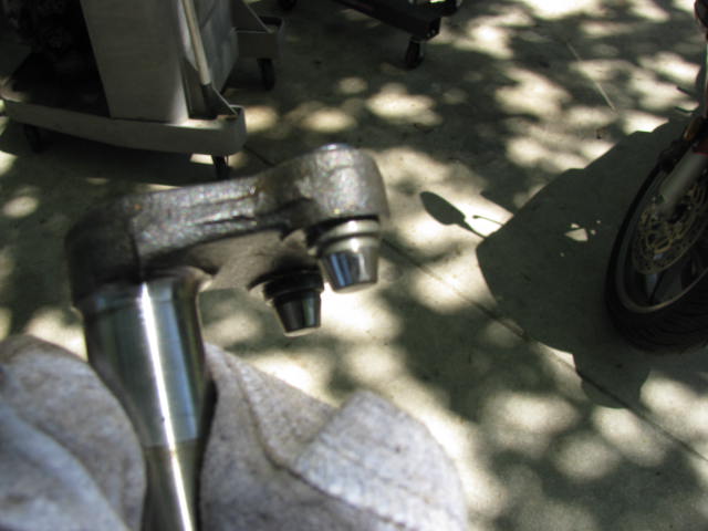
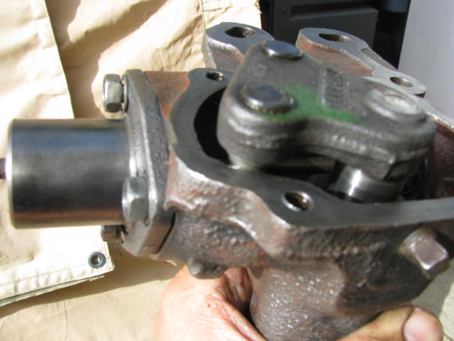
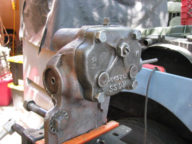
Here, we see the placement of the steering box, relative to the master cylinder. There is no part of this Willys that hasn't been messed with at one time or another. From this brief inspection I now know that at the very least, this steering box will require a new sector shaft and prudence dictates the replacement of the pitman arm as well. So, if we're going that far into this steering box, the intelligent thing to do is get a full rebuild kit - bearings, bushings, seals - the works. It's an easy job and as I said before, good steering on any vehicle is a lot of value added. any money that goes into improving steering is money well spent.
Now, removing the steering box at this point is ridiculously easy. We've no engine and transmission in the way and there's a large gaping hole in the floor so the steering wheel doesn't have to come off and there will be no finagling to do to get it out. BUT - now is a very good time to wrestle with this steering wheel hub nut because everything is bolted up and it's right where it's easy to work on.
In this next segment I'm going to be writing about little tricks you can employ to get around certain common problems. These are tricks that don't involve large hammers and brute force.
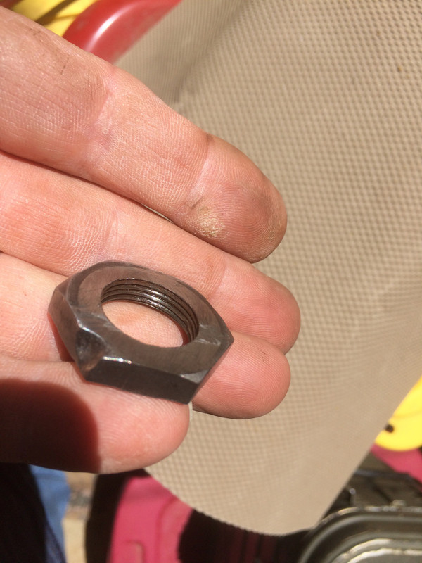
I knew this nut was going to be a booger from day one and I have been laying on the PB Blaster now and again since we brought this truck home. I also know that this is a standard fine-thread nut (righty-tighty, lefty-loosy). I've turned the steering wheel hard over and put a big wrench on it and it won't budge. I could put an impact wrench on it but the problem with that is, this part of the steering column is rather fragile, everything may be entirely rust-welded together and forcing it may very well destroy the threaded end. There are simply too many unknowns, so, I am fully invested in the notion that it is best to cut that nut off rather than strong-arm it.
Now my experience with fine threads is that rust usually gets no further than the first one or two turns of thread and while it's enough to hang things up, one or two turns really ain't much. But we are dealing with a steering wheel that is, in my opinion, still salvageable and putting heat on there just isn't a very good idea. In fact, I dare say it's NEVER a good idea to heat that area up with a torch, owing to the fragile nature of the threaded end of the steering column (which is also all the more fragile because it is hollow and rusty on the inside.) But before I start cutting the nut....
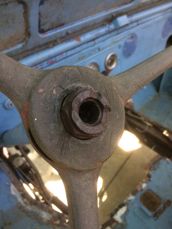
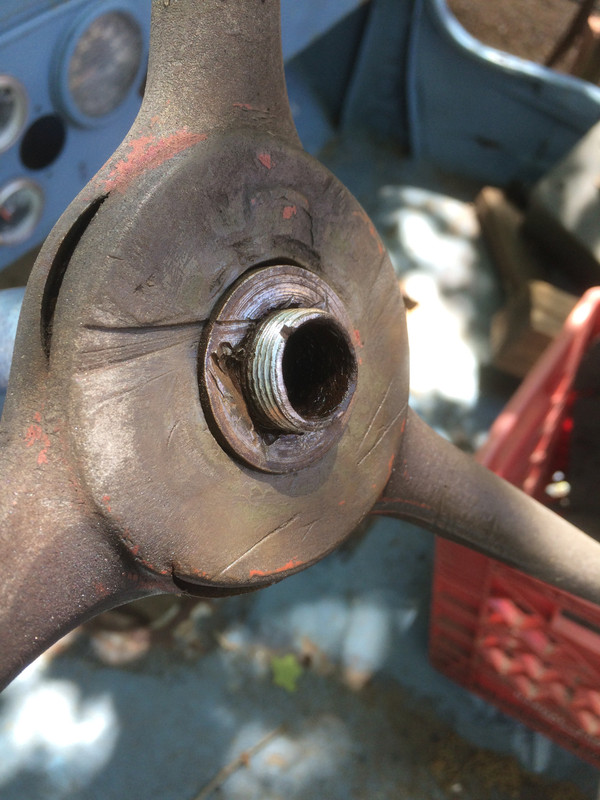
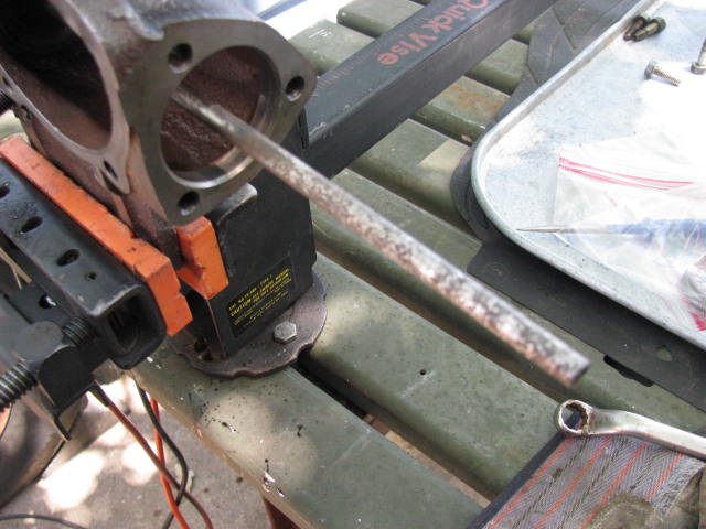
I'm going to start removing the lip that the horn button hooks onto. I'm doing this with a cutting disc which allows a great deal of control and with a light touch, it removes a small amount of material at a time. While this lip does not engage the threads within the nut it is right where the turns of the thread start. Friction creates a pretty fair amount of heat and this heat is going to end up EXACTLY where I want it. Maybe I'll get lucky!
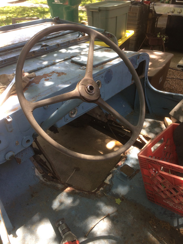
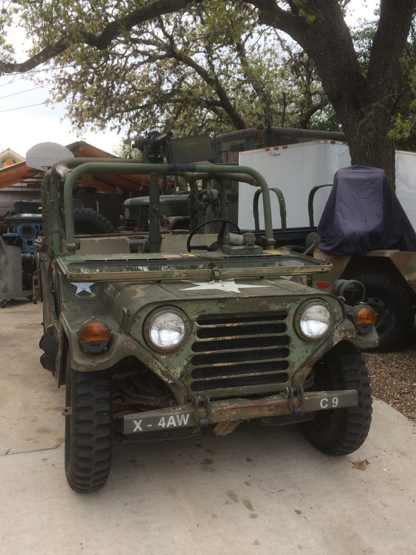
Stepping back to take a sip of coffee and wait for the air compressor to catch up. These old Willys are very attractive in their own way.
No rush and nicely done. Far better than wailing away with a hammer, eh?
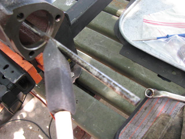
Immediate and positive results! The heat from the friction broke the rust-bond. Look at that rust!
There's plenty of evidence this isn't the first time someone has attempted to remove this steering wheel. I think more dosing with PB Blaster is in order.
There's that nice large hole we'll be using to take the whole thing out for a rebuild.
If you look at this photo closely, you'll see I was right about the rust. Almost all of it is in the first turn of the threads.
Cheers,
TJ
Last edited by m3a1 on Tue Apr 17, 2018 10:04 am; edited 6 times in total
That's actually an Alley Cat body with MUTT guts. They're built like a tank.
Well, we'll just have to make the most of the weather. I've got a ton of things to do on this Willys and the way things are going, I'm going to need every day of sunshine I can get.
Most of you have long experience with these old trucks so what I'm about to post will be old news so what follows is really for some of you who might be new to all of this -
On the topic of removing the steering wheel. First of all, you aren't going to get that steering wheel off by wobbling it off. The tolerances between the steering wheel and the steering shaft are extremely fine. When everything is in good shape there is no wriggle room - thus, the steering wheel must be drawn off in a straight line. If your steering wheel DOES wobble, all bets are off and you're going to be replacing steering wheel and the shaft altogether.
I've read some of the many posts on this site detailing other people's efforts to remove steering wheels and everyone seems to agree that it is usually a real man's job to get 'em off, owing to the nature of these vehicles. These trucks are often left out in the weather with no top and the horn button cup rotted out. It's just the perfect set of circumstances to make things hard for the guy who wants or needs to have that steering wheel removed.
On steering columns such as are found on these old trucks, ones that are a hollow shaft with a threaded end it is quite possible to ruin that threaded end when using a puller. Why? Because the threads are cut into the shaft which is already quite thin at that point and extreme pressure placed upon that area can actually compress the turns in the thread upon each other, like an accordion.
Therefore, great care must be taken to protect those threads and that can be done in several ways but the most logical way would be to ensure that the nut is threaded nearly all the way back on after having been doped up with a good lubricant. It should be threaded almost all the way back on leaving a very small gap below it, allowing a small space for the steering wheel hub to be drawn up into. Getting a steering wheel to break free actually happens with very little upward movement and once that is accomplished the rest of the removal usually doesn't require any great pressure from a puller. But for the initial pull, the more threads you have engaged in the nut, the safer you are.
Also, if you are new to using a puller, there must be something for the puller to center upon and whatever that something is, it must rest upon the nut you're using to keep the threads from collapsing. Nothing should be pressing against any actual part of the steering shaft.
Before you make the effort, it is also important to know that this is a job that might take some time to accomplish. So, if you are renting a puller, you should know that this may be a job that takes some time. It may also take some finesse and by that I mean it may require great patience. This is one of those jobs where it may be best that you put suitable pressure on the part with your puller and walk away and let time and gentle variances in temperature throughout the day work their magic.
There are several little tricks that can be added to the mix that may help a steering wheel let go. Lubrication, temperature variables between parts and vibration.
Lubrication may or may not help. These tolerances are such that very little lubrication can migrate into the fit between shaft and hub. That said, lubrication after the moment when things break loose certainly can't hurt.
Temperature variables have been employed and discussed extensively in other posts on this site and they have been used with some success.
What never seems to make it into print is giving consideration to shocking the part. Remember the old trick of getting a ball joint or a tie rod end to let go by striking it simultaneously from both sides? Obviously you can't hit those hard enough to deform anything but the shock vibration set up by that works miracles on parts with interference fits.
If you have an old steering wheel like mine, one that's going to need a refinish no matter what, there is really nothing preventing you from carefully drilling two holes through the resin on either side of the steering wheel hub; holes big enough for a good sized punch or bolt or something similar to rest against the actual metal of the steering wheel hub. Then, with a puller putting stress on the steering wheel, a simultaneous strike on those punches from opposite sides is a very effective way to shock the hub right where it counts.
Fixing the holes in the resin is a simple matter of filling and sanding. So, I may use this method on this truck if the steering wheel resists coming off. However this goes, you will see the process in a future update.
Cheers,
TJ
Last edited by m3a1 on Tue Apr 17, 2018 7:04 pm; edited 2 times in total
Ok, after I posted my last post I was thinking some of you were probably quietly saying to yourself, "HEY! This guy is nuts, talking about drilling holes in steering wheels and improvising stuff" So, for those of you who are from Missouri (the Show Me state) I decided if this steering wheel was giving me any resistance at all, I would go that route and show you.
But first, let's talk about a couple of other things. The biggest problem with pulling a steering wheel (meaning one that is not cooperating) is that there is really no way to tell when you almost have it. Thus, many people just cross their fingers and keep cranking down on that puller until they meet with success, or until they ruin something and I will admit, today I felt the call to crank that puppy down just....one....more.....turn, just as I always do. Happily, I've learned to resist that urge and that is something you must learn to do as well. Resist the urge to strong arm things! But, when you've reached that point when you've got enough pressure and things still aren't moving -and- you have given it the time to let go -and- you've run out of all other options, shocking that hub will get it off.
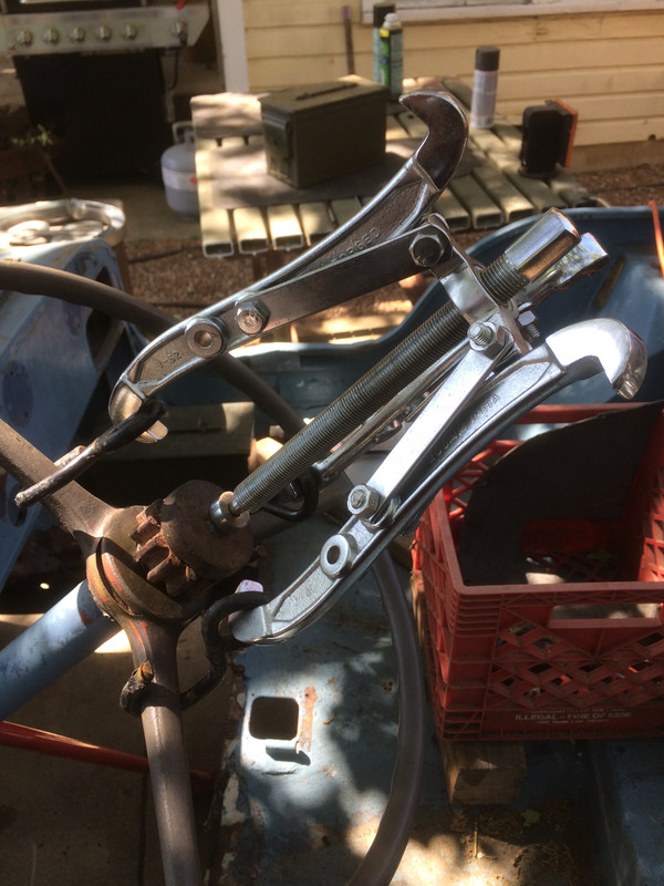
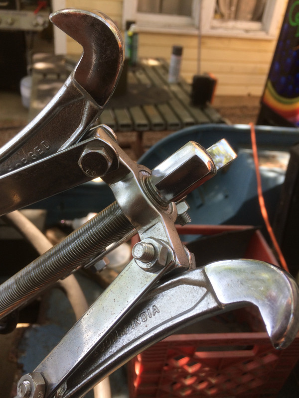
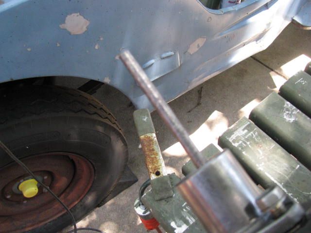
Second, the old adage, There is more than one way to skin a cat is very true and with what you are about to see is something that may have you rolling your eyes at first. The rig I set up admittedly looked like a freak show but it worked quite well, it had a little give built into it and it did the job. Yes, it would have been easy to trot down to O'Reilly's, borrow the perfect tool but that would have been too easy and we wouldn't have learned anything and I wouldn't have had much to write about. Boring! ...and no fun at all.
Besides, some of you live out in the middle of no where and may not have certain resources available to you, such as an auto parts store on every corner. I'm a pack rat by nature and you will see that I am using several ratchet strap hooks that I found here and there along the interstate. I also used an old gear because it was very stout and the disc on top of that is from a 75mm artillery shell; a piece I picked up on an old firing range. About that piece - first, artillery shells are made from very high quality steel that is as hard as woodpecker lips and this piece happens to have a very nice bit the middle that was perfect for centering the puller and keeping it there.
So, here's my rig. Very few turns are left on that puller but what's there is more than enough to do the job. The puller is set up for as straight a pull as I can get with the hooks nicely in line with the draw point of the puller. The hooks are not quite directly in line below the draw point owing to the their size and the size of the steering wheel spokes which flare closer to the hub. Still, it's a very pretty line and almost parallel to the line of the steering column. The closer you can get to that line, the better off you are.
DO take the time to get this set-up right. It will pay big dividends.
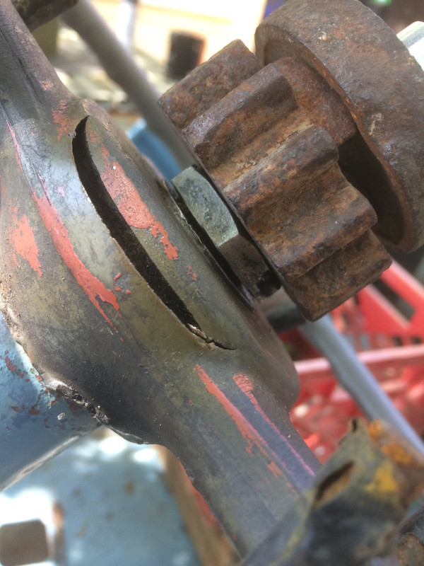
In the following photo, the original retaining nut for the steering wheel has been threaded on to a depth where none of the threads of the steering column are directly exposed to anything and the nut is about 1/16' above the hub of the steering wheel. The nut is taking the load and transmitting that energy past the threads we really care about preserving (those at the top). That 1/16" gap is all the movement we're looking for at this point. By the way, the large circumferential crack existed on this steering wheel before we began.
Here you will see I've drilled a 3/8" hole and there will be another drilled on the other side. I went with 3/8" because a bolt that big is big enough to take a good whack with a hammer and transmit that energy straight to the hub without risk of bending. The large cracks were already there. When contemplating whether or not to drill holes in your steering wheel, it's not a hard decision to make when the steering wheel is already buggered. Might be a harder decision to make if you have a nice, pretty one, eh? Still, holes such as these are easy to fill with binary plastic resins available at just about any reputable parts store.
You may notice that the ring at the top of the hook is opening, but only ever so slightly. This will give way before anything breaks and puts my eye out! At least that's the theory. I might just as easily have first taken these over to my welder and welded the loops on the hooks closed but I had a feeling they'd hold up just fine....and they did.
Gap closed! It took about ten simultaneous strikes on the two opposing bolts and with an audible *POP* that hub slid right up against the retaining nut. Ahh! Sweet success! Shock WORKS and works well.
As you can see from the number of turns, I applied quite a bit of pressure to that thing before it gave up.
In rust, we trust!
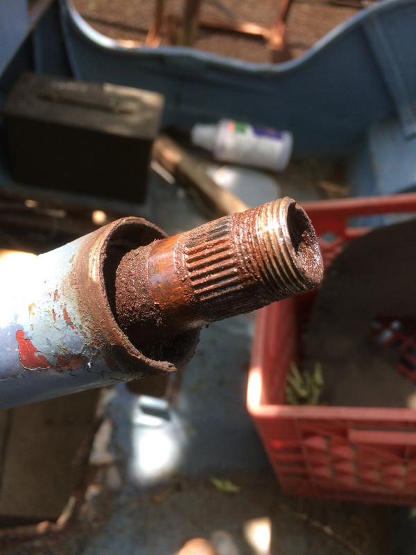
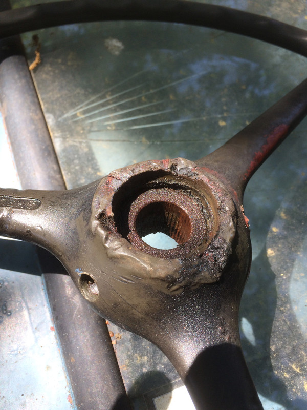
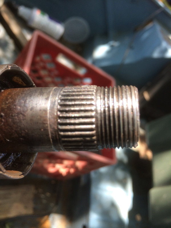
I was fully prepared to refinish this steering wheel but quite frankly, I don't like the look of those hub splines. New steering wheels are rather inexpensive and safety is our number one priority. I'll probably just clean this steering wheel up and make a wall hanger out of it, just for giggles. Somebody really beat the tar out of this thing at some point. As you can see from this photo, there is really no sense in hammering on the lower regions of the steering wheel. It's just plastic. Also, take note of the diameter of the hub as compared to the diameter of the steering column's outer tube. There is simply no way to get force up against the hub from below.
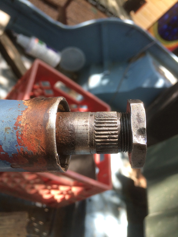
Here's the top. No, that's not a washer. That's the top of the hub.
Take a good look at those lower threads. Those lower threads are not important to us. Now I know y'all wanna get right in there and tidy everything up to absolute cleanliness but, consider this. That retaining nut is never going to be that far down on those threads -and- the pressure from the puller has very likely compressed those threads somewhat because they did not have the support that the top threads had with the nut in place. Give them a cursory clean up but don't worry about being able to run the retaining nut all the way down those threads. It's never going to have to go that far.
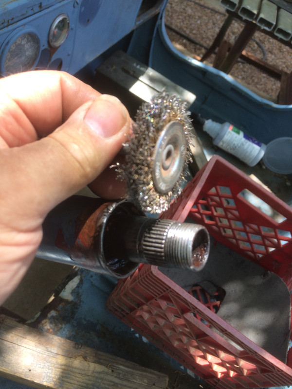
What you are looking at is a HUGE NO-NO. If you want to use a steel wire brush on the threads, that's OK -but- don't use that on the splines, particularly at right angles to the cut of the splines. Far better to use a brass wire wheel which is being run in-line with the splines. Use something soft and forgiving and don't ruin those splines!!!
Notice the interference fit below the splines? that's where a lot of the hang-up is when the steering wheel is bolted up.
Thanks for looking!
Cheers,
TJ
Last edited by m3a1 on Sat Apr 21, 2018 10:59 am; edited 2 times in total
Keeping in mind the last problem I had with mail order (remember the bearing cup substituted for a bearing and concealed in the bearing box?) I dutifully checked the whole order and found I was missing two minor pieces. I called the guys, politely discussed it and they were very good Joes and all about making it right. I realize mistakes can and will be made and their professionalism will ensure I do business with them again.
Their picker just missed a few little retaining clips and since I wasn't really ready to jump in on this installation just yet, no time lost. The provider is sending some replacement pieces along. I'll soon be removing that steering box and it'll be like Christmas...we'll all get to see what's inside! Yay!
Ok! My son and I removed the steering box this evening and it took about five minutes. That went very quickly owing largely to the fact that there is no driveline in the way and one of us worked inside the engine bay while the other worked outside.
We removed the three bolts securing the box to the frame (taking care to keep track of the shims that help align the steering box in relation to the frame and the body) and two bolts at the base of the dash panel. Owing to the rather aged condition of the body's mounting points, remounting the steering box may just be a simple reinstall just as it was, or it may require more thought. We shall see when the time comes.
I do not mention making any reference marks for reassembly (to keep the pitman arm and sector shaft aligned as they were) because both the shaft and the pitman arm will, most likely, end up on the scrap heap so, reference marks would be a wasted effort.
However, if you ARE going to reuse these components on your truck, marking them would be a very good idea.
Anyway, the box is off and tomorrow I'll start by cleaning up the externals of the box before we disassemble it.
Keeping these shims located where they came from throughout the overhaul of this steering gearbox is important if everything is expected to go back just the way it came off.
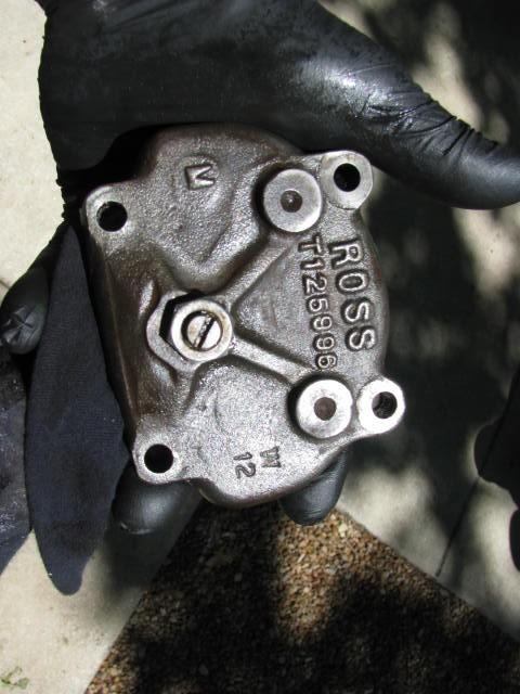
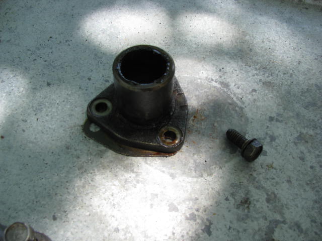
I just went at this with the drill and a cupped wire brush and knocked off most of the junk before getting into the internals. At the outside and bottom of the gearbox (that part that is closest to the ground when it is bolted to the frame) is the end of the oil tube that serves to allow the horn circuit wire to pass through the gearbox. This oil tube is actually rather frail and it attaches by being peened over on the cup at the bottom of the gearbox so, go easy when you're cleaning up that area and don't be too aggressive with whatever tool you might be using.
Speaking of clean-up. The oil tube is just about .22 cal so if you have a bore brush, it will do a very nice job of cleaning up the interior of the tube. Just be sure to support it well while you're cleaning it out.
Also, once you have the steering shaft removed from the gearbox, this tube will be totally unprotected and it sticks out of the gearbox quite a bit. Be extra careful not to damage it and whatever you do, don't drop the housing!
Some of these bolts pass through the housing and into the interior of the gearbox and these bolts will require sealant when we close up the box for good. Otherwise, the lubricant will migrate up the threads and out of the box. By the way, these bolts have a soft, flat washer without a lock washer. I'm sure the theory was that would help keep a good seal.
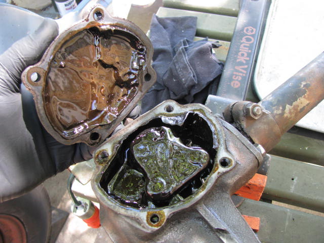
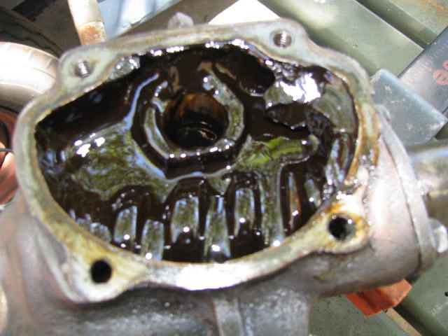
With the bolts removed and a gentle tap, the cover comes off. Yes, it looks nasty and someone even introduced some grease into this box (which is a no-no) but what I don't see is any milky lube so I'm betting things are going to be pretty good down in there.
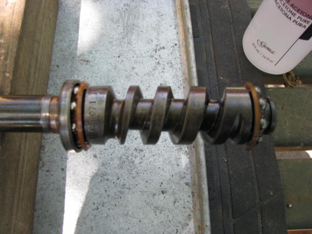
Luckily, despite the fact that the steering gear shaft was open to the elements, it was filled with dirt - so much so that water just never got down into the gearbox.
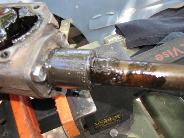
Off comes the steering column's outer tube, the Steering Gear Jacket. I made a mistake last night when I laid this whole thing down on its side and because of the angle it was at, some of that lube made it up into the steering column. So, I made some extra work for myself - additional cleanup. Bummer.
Original gasket still in place and some of the thread sealer can be seen, still on the inside of the cover.
Pitman Arm Adjusting Screw and lock nut.
Pitman Arm Shaft coming up and out.
Some wear on the tapered studs but this is just about what I'd expect from a 67 year old truck.
Goopy, rather ugly looking lube, but actually, it's still just about the right consistency - very much like the consistency of honey.
Upper Housing Cover. This has shims beneath it and these are what set the end play of the steering gear shaft. The three bolts that hold it on are to be torqued to spec so before you reassemble, ensure that you have good, healthy bolts.
With a variety of shims (and I've ordered a kit that comes with shims) what you are trying to achieve is a steering gear shaft that moves freely and yet has no end play, meaning the steering gear shaft moves neither up, nor down.
Why not just use the combined shims that came on this box? Well, I'll be replacing the ball bearings and perhaps even the upper bearing cup so that may very well change the height of the steering gear shaft relative to the housing. We shall see.
Upon reassembly, I'll be shooting for "no end play" which seems rather definite and leave the rather vague interpretation of "moves freely" out of it. We just know we don't want it bound up. As with we did with setting the preload of the king pin bearings, it will likely take several tries to get it just right, which is really no big deal as all of that will take place on the work bench. My old back can use a few easy jobs.
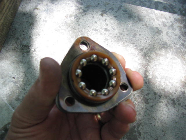
It is very important that you take good care of these shims while everything is apart. Now we are almost ready to take the steering shaft out of the housing. There are going to be ball bearings in the next step - possibly loose ones. You should find them organized in a rather clever little plastic retaining ring but beware - anything is possible on these older trucks. Take great care to make sure not to lose any ball bearings before removing the steering shaft from the housing!
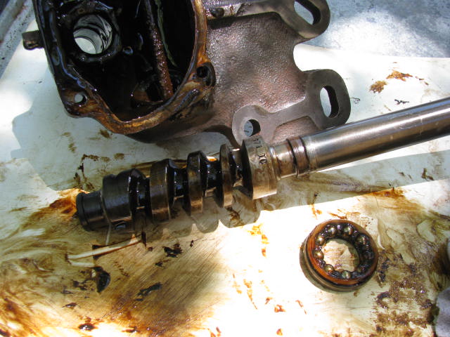
With the Pitman Arm Shaft and the Upper Housing Cover (and shims) removed it is now possible to draw the Steering Shaft directly up and out of the housing. In doing so, the Cam Shaft Cup (which is the cup for the ball bearings) and ball bearings will come with it as they are laying on top of the Steering Gear Cam Shaft (the worm gear).
Things are probably slathered in lube so it will be hard to determine what is going on with those bearings. My suggestion is that you prepare for the worst case scenario and be working over a tray of some kind and maybe even a magnet just in case. Wrap those bearings with a rag as soon as they clear the top of the gearbox housing and keep them secure. If they are still arranged in their plastic retaining ring, carefully draw them and the bearing cup up and off the steering gear shaft.
In this photo, you can see I have removed the bearings and their cup so you can get a better look at them. These might be something you want to re-use but some of the rebuild kits will offer you sets of new ones so if things go badly, don't panic. Replacements can be had.
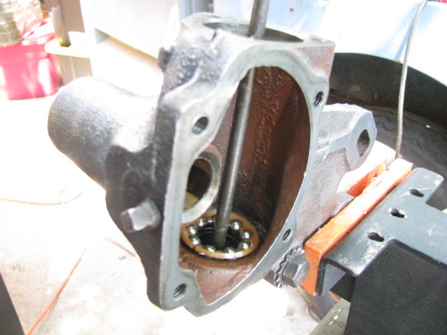
Now, the oil tube I described earlier, shown here as it resides inside the housing except that when everything is assembled, the oil tube is inside the Steering Gear Shaft. The sump at the far right of this photo is pretty much the lowest point in the gearbox. There was quite a bit of dirt and grime in there, but happily, no rust.
Immediately above that sump is the lower bearing cup. The lower ball bearings are organized in a plastic ring just like the upper bearings and they sit in that bearing cup and the base of the Steering Gear Cam (worm gear) rests upon them.
See the Pitman Arm Shaft bearing? It is a bushing-type bearing of yellow metal. There is a shadow on it which is a wear pattern. There's a lot of load on those bearings when things are turning and it is very important that they be as good as they can be. These will be replaced and I'll show the removal process in detail. Because there are yellow metals in the steering gear box I will need to ensure the new lubricant I use will not harm them over time. Some of the more modern formulas will. At this point I don't know exactly what I am going to use but I can tell you that this is NOT the place for 90wt, nor is it the place for chassis grease!
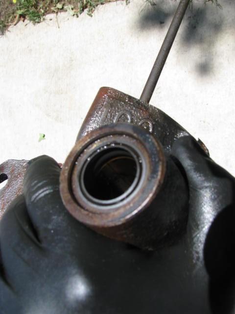
Pitman Arm Shaft oil seal. This one has held up extraordinarily well over the years and has done its job proudly even though the bushings are worn. I know what you want to ask. Could we get by with reusing the bushings if the oil seal has been able to accommodate the wear? The answer is, Yes...but only until the wear becomes too great and we are quite clearly headed in that direction, right? I don't know where the tipping point is and I don't want to have to find out after I've put everything back together. Better to replace these bushings and seals now and be done with it.
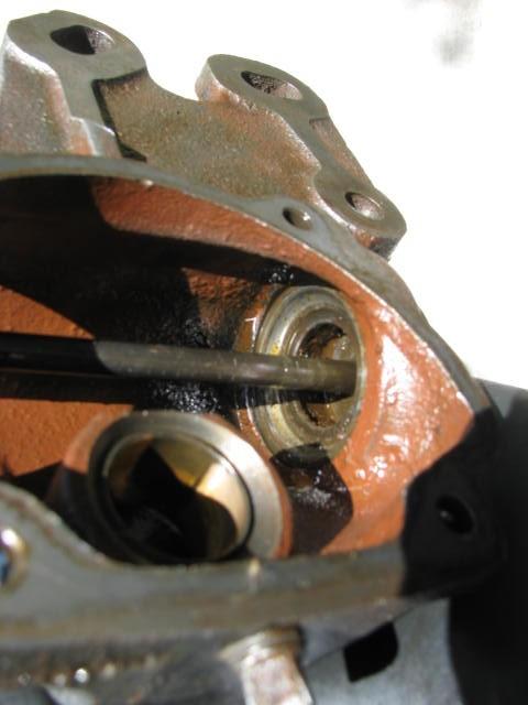
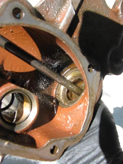
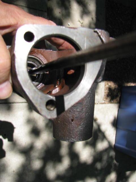
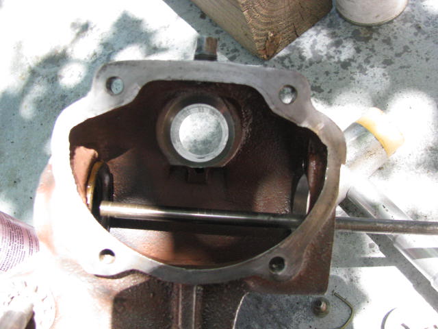
I apologize for the photo and I'll try to remember to retake this one. Have a look at the opening where the Pitman Arm Shaft passes through the housing. There are two bushings (or bearings); an inner and an outer with a gap between them. One bushing is a long bushing and the other, a shorter bushing. In the space between those two bushings there is a passage in the casting (in the photo, it's at about the 1 o'clock position) and that passage allows lubricant to get into the gap between the two bushings so as to lube the Pitman Arm Shaft. In the event you install replacement bushings in the wrong order, the longer bushing will very likely cover that hole. Something to think about.
Here is the result of having a Pitman Arm installed off-center. *CLUNK* The Pitman Arm Shaft goes full over and the tapered stud bangs into the interior of the casting before the steering knuckle hits the stops. The TM says to count the number of turns lock to lock and come back half that to ensure the gearbox is centered before installing the Pitman Arm. Don't skip that step!
And there's the dent where the tapered stud had been hitting. I'm quite sure this is very old damage as the steering has been fairly well centered since we got it and both sides went all the way to the stops but at some point, somebody had screwed it up.
One of the benefits of NOT having all the parts ready to go is it forces you to slow your roll. So I spent today doing all the extra things that were needed to make this part of the Willys project go in the right direction.
Today was the final disassembly and cleaning of the steering gearbox. There were a lot of things to do and it took quite a bit of time to get it done.
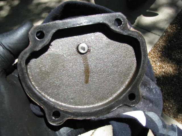
As promised, here are a couple of pictures of the oil tube as it secures to the cap at the end of the steering gearbox. My comment earlier was, upon cleanup, be careful around this end of the tube so as not to damage it. Oil Tube is something of a misnomer as this tube is not used to conduct oil anywhere. Rather, it acts as a passageway through the gearbox.
Here we have the Steering Gear Cam with its supporting bearings properly oriented. The top (left) has the bearing cup in place (the bottom's bearing cup is still in the housing).
The ball bearings can be popped out of the ring that organizes them and new balls popped back in. I'll be replacing them all. The top ball bearings look great. The bottom ball bearings look dull and have some very tiny rust spots on them.
The oil pipe extends well up into the steering shaft and terminates well above the oil bath in the steering gearbox. Thus, a good portion of the oil tube is subject to rust and corrosion.
I didn't mention the washers on these bolts yesterday but like the ones on the side cover, they are also flat washers, rather than lock washers.
Here is the top bearing cup, properly oriented to the housing.
Upper Housing Cover, upon which rests assorted shims....
....and the upper Cam Shaft Thrust Cup (bearing cup). The Upper Housing Cover presses upon the upper Cam Shaft Thrust Cup and the shims limit how much force it can exert upon the Cam Shaft Thrust Cup.
....and the upper bearings.
And here we have the lower Cam Shaft Thrust Cup (bearing cup) and bearings oriented properly within the housing.
Now is a very good time to loosen the pipe plug which always seem to be screwed in too tight. Do the next guy a favor. Use a little thread sealer and don't screw it in gorilla tight.
The next two shots are of the oil passage from the internals of the housing to the area between the two bearings for the Pitman Arm Shaft.
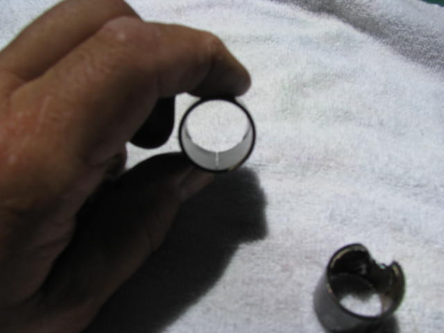
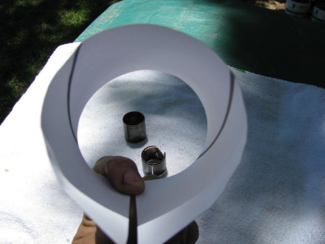
Ok, here is where I ran into a little difficulty and there is some important information for you in the next set of photos. I tried to follow the removal procedure for the Pitman Arm Shaft Bearings, as set forth in the TM but could not find where the bearing was bisected which would have been the correct place to begin. As a result, I found I was simply drifting the inner bearing down and against the other bearing. But things WERE moving. So, rather than blindly follow through with what was clearly turning out to be a bad effort I got a socket of a suitable size and pressed both bearings straight out.
At the far end of the bearing you can see where the two helical grooves are cut into the inside of the bearing. Precisely half way between those grooves is where the bearing is bisected. You may not be able to see that bisection when the bearing is in place, but now you know where it is. Unfortunately, I didn't have that information. No harm done though and as we said before, there is more than one way to skin a cat!
This paper is a mock-up of the bearing so that what I just described may be more easily seen.
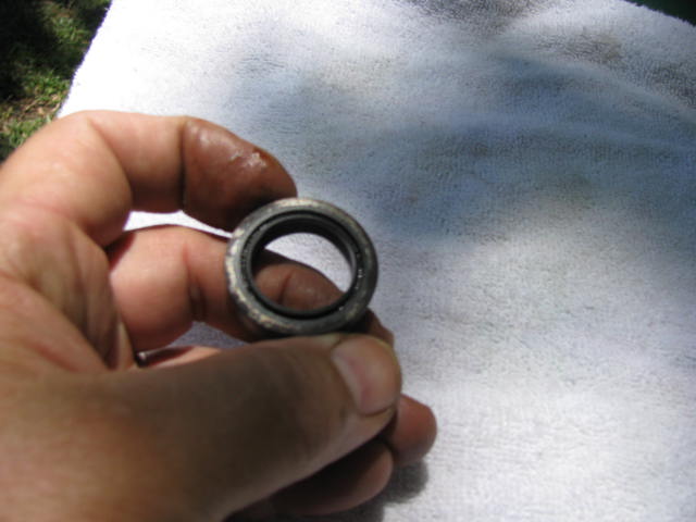
This surprised me. Except for the metal you see on the top face of this seal (which is a small washer to which the rubber seal has been vulcanized) everything else is rubber; the seal face, the sides, the whole bit. But, when you consider this is just to seal a shaft that turns only a few degrees this way and that, this is really all you'd need, eh? With this manner of construction there is something to consider and that is, when installing a new seal, it may be in your best interest to put some light adhesive in place where the sides of the seal rest against the housing.
We will be removing that bearing cup, I promise!
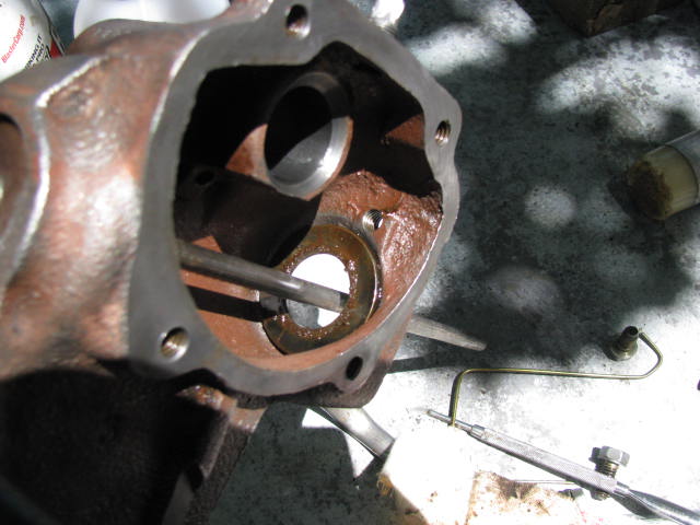
And here is how it looks with the Pitman Arm Shaft bearings and seal removed. There's the all-important hole for lubrication.
Back to the oil pipe. The end that exists outside the oil bath has become rusty and we need to put a stop to that.
So, an application of Ospho (phosphoric acid) gets laid on and allowed to work it's magic. I may lay on a thin coating of varnish before reassembly.
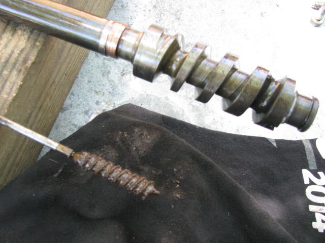
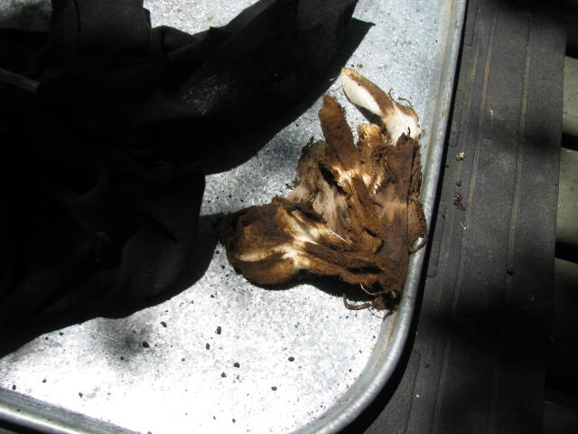
And since the reason for that rust is because the interior of the Steering Gear Shaft has become clogged with dirt and rust and all sorts of junk. The best way to deal with it is to treat it just as you would a rifle barrel.
I spent about two hours on sorting this out. I used everything from PB Blaster to Gunscrubber, acetone....the works. The process terminated with a final scrubbing with hot, soapy water and a high pressure rinse. I then laid it out in the sun on an incline until everything dried and then laid on a generous application of metal preservative. Two hours seems like a lot but I think it was time well spent.
Initially, that bore brush was coming out completely full of junk! All this work because someone couldn't bring themselves to spend a few measly dollars on a replacement horn button. Of course, with some of the low quality reproduction stuff coming out, I really don't expect my new horn button to last, either. You can be sure of one thing. I'm going to do my level best to ensure the interior of this stays clean and dry from now on.
Here's a huge pile of rather nasty looking patches from swabbing out the bore of the steering gear shaft.
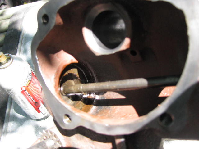
The moment you've all been waiting for. The lower bearing cup is coming out. I inverted the housing and with a dead blow hammer, stuck the bottom of the housing. Inertia brings the bearing cup out. It is a very fine tolerance and PB Blaster can be a big help in this process. If your housing is rusty down there you may have to engineer a way to pull it out but however you remove it, it has to come out perfectly straight.
It is exactly the same size as the upper bearing cup.
As we can see, there's still a lot of crud down in there to be cleaned out. Parts are on the way and we'll soon be into the reassembly.
Has this been hard work? Absolutely not. Could anyone with basic mechanical skills do it? Sure! Does it require special tools? Nope. So, if you have a steering gearbox that needs a do-over my recommendation is - DO IT!
Cheers,
TJ
Last edited by m3a1 on Sun Apr 29, 2018 11:59 pm; edited 2 times in total
Nice presentation TJ. I only see two items missing.
I did not see any reference to technical data.
I know a lot of us old timers roll up our sleeves and hit a familiar task with great enthusiasm and don't see any mystery but the target audience here is not only looking for the how of it but would also like to know where it is all written down so they can access it when needed 5 or 6 years from now when they decide to do theirs.
The 2 items are:
It's great we have folks to show newcomers the way but we must also show them the manuals. If we don't they will never use them. _________________ Wes K
45 MB, 51 M38, 54 M37, 66 M101A1, 60 CJ5, 76 DJ5D, 47Bantam T3-C & 5? M100
You cannot post new topics in this forum You cannot reply to topics in this forum You cannot edit your posts in this forum You cannot delete your posts in this forum You cannot vote in polls in this forum