Joined: Nov 01, 2017 Posts: 135 Location: Richmond, BC Canada
Posted: Sat May 18, 2019 2:36 pm Post subject: M38 24 volt electronic ignition
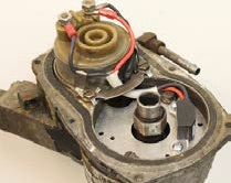
Can someone please post a picture showing how the leads are connected.
Specifically, how does the positive lead attached together with the existing positive lead?? _________________ Lyle
LT-RCEME, Retired
________________
Jeep Rubicon, 2015
M38 CDN, 1952
M416, 1968
I can be a stickler for the details sometimes. By that I mean I prefer to call electronic ignition, systems that actually control the spark as well as other operating parameters of an internal combustion engine by managing the entire engine electronically. There are three systems for the Willys/Kaiser 134 series engines that are often confused with full blown "Electronic Ignition Systems", which by the way did not make their entry into production automobiles until the mid 1970's, and they have a lot more control over the engine.
1 - The aftermarket Pertronics system which is simply a hall effect electrical contact replacement system That replaces the mechanical points with an Electrical hall effect RELAY This allows less frequent maintenance of the ignition system. Often this system is bragged on to in some magical way increase performance but in reality all you have accomplished is to extend the necessary visit frequency to the distributor resulting in more troublefree miles of service.
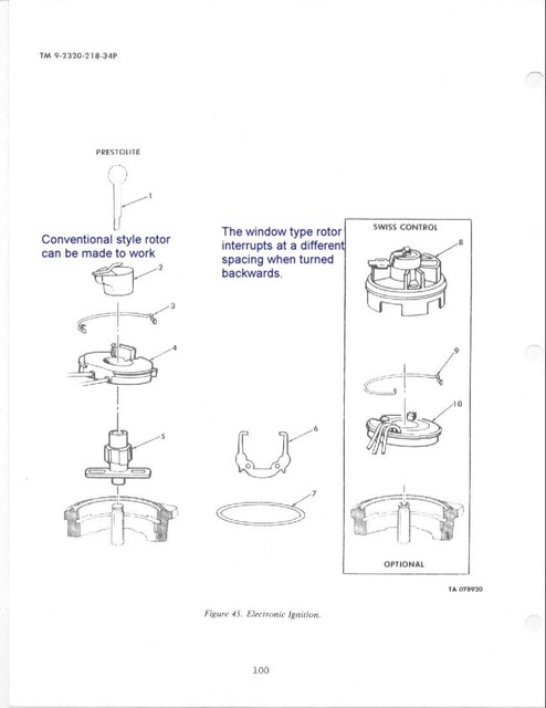
2 - Was the early Prestolite mechanical points replacement Electrical Hall Effect Relay System which functions the same as the Pertronics and was introduced on the Early M151 jeeps. Often this system is bragged on to in some magical way increase performance but in reality all you have accomplished is to extend the necessary visit frequency to the distributor resulting in more troublefree miles of service.
3 - Was the late syle Swiss Controls mechanical points replacement Electrical Hall Effect Relay System which functions the same as the Pertronics and was introduced on the later M151 jeeps. Often this system is bragged on to in some magical way increase performance but in reality all you have accomplished is to extend the necessary visit frequency to the distributor resulting in more troublefree miles of service.
Notice the three technical descriptions of the three systems is virtually identicle!
I know, you are probably getting bored with this lesson however I thought it was important for us to properly answer your question since we need to know which system you are referring to. _________________ Wes K
45 MB, 51 M38, 54 M37, 66 M101A1, 60 CJ5, 76 DJ5D, 47Bantam T3-C & 5? M100
Joined: Nov 01, 2017 Posts: 135 Location: Richmond, BC Canada
Posted: Sat May 18, 2019 4:30 pm Post subject:
Thank you...... I just needed to confirm how and where to connect the positive.
Quick question, since the Pertronics MV-141A only wants 4-6 volts, Ive calculated that a 6 ohm ballast resistor in the ignition wire prior to distributor? _________________ Lyle
LT-RCEME, Retired
________________
Jeep Rubicon, 2015
M38 CDN, 1952
M416, 1968
Last time I looked which was some time ago Pertronics offered a 24V unit. Why are you adapting voltages to reduce to 4 or 6 volts? The Pertronics MV-141A instructions do not require that. The instructions do point out the kit is designed to function with a coil that has built in resistance of 7 to 8 Ohms. The coil in your IAU series distributor has an internal resistance of 5.3 to 5.5 Ohms. Perhaps you are trying to raise that figure a couple of ohms???
The wire #12 routing does not change just because you are using an electrical Hall effect relay to replace your points. The #12 lead sets piggy back on the coil + post with the Pertronics red wire. There are some minor adjustments if you decide to drop the noise filter capacitor in addition to the condenser. If you look in my photo album under Ignition Systems you'll see a suggested method for eliminating the radio noise filter capacitor.
Quote:
GTIN Code: 694342534899
MFG. Part #: MV-141A
EO#: D-57-22
Info
For over thirty years, the Ignitor has proven itself in applications ranging from race cars to tractors. The Ignitor replaces breaker point and troublesome factory electronic ignitions with a dependable, self contained and maintenance free electronic ignition system. The Ignitor has been called the "stealth" ignition because of its quick installation and nearly undetectable presence under your distributor cap.
Features
Operating Voltage: 8-V to 28-V DC
Temperature Range: -50 to 300F
RPM Range: 0 to 15,000 RPM
Can be used with most point-type coils, optimal performance achieved when used with our Flame-Thrower 40,000 volt coil.
Works great in stock point-type distributors as a trigger for multi-spark CD ignitions, eliminating the need for expensive aftermarket distributors.
No complicated wiring makes installation easy.
A solid-state electronic ignition system. "Never change points again!"
Application
All M39, and M422 V4 (24-volt system, Mil-Spec Waterproof Ignition, Not for use with solid core spark plug wires)
Notes
PerTronix MV-141A Ignitor Autolite 4 cyl 24 Volt Negative Ground
Delivers twice the voltage to the spark plugs, increasing horsepower, fuel economy, and spark plug life
2:1 improvement over points in current fall time for increased coil output
Rotating cobalt magnets trigger a Hall Effect integrated circuit . ...no points to burn, ...no moving parts to wear out
Epoxy molding makes our module impervious to dirt, oil, grease and moisture
Fits entirely inside the distributor
No "black box to clutter the engine compartment
Stable timing ...no need for any adjustments
Will trigger most multi-spark CD ignitions
Available for 6 and 12-volt negative and positive ground systems
Legal in all 50 states and Canada (C.A.R.B. E.O. #D-57-2)
Charts
Pertronix Ignitor I/II/III Comparison Chart
Some parts are not legal for use in California or other states with similar laws/regulations
Joined: Nov 01, 2017 Posts: 135 Location: Richmond, BC Canada
Posted: Mon May 20, 2019 2:25 pm Post subject:
Wes:
Thx for your info.
The minimum of 7-8 ohms with a resistive type coil.
I called Pertronics tech support and they stated that the MV-141As optimal voltage at the igniter (pick-up) is at 4-6 volts and that a ballast resistor must be used to reduce the igniters signal Voltage to that level.
Coils, I know the document from Autolite if there is an internal resistance and if so what value it is.
You are quoting the CO type coil with that internal resistance.
I have the CT type coil and it has zero internal resistance. Therefore I need to add the ballast resistor with a value the reduce the existing 24 volts to 4-6 volts.
Seems odd that a CT coil used in a M38 at 24V without any in line resistance can be suddenly connected to a ballast resistor reducing it's input voltage by 18V's and expected to still perform adequately for the same spark plugs! _________________ Wes K
45 MB, 51 M38, 54 M37, 66 M101A1, 60 CJ5, 76 DJ5D, 47Bantam T3-C & 5? M100
Joined: Nov 01, 2017 Posts: 135 Location: Richmond, BC Canada
Posted: Tue May 21, 2019 12:02 pm Post subject:
Wes:
No magic. I simply looked at the document http://willysmjeeps.com/downloads/Ignition.Coil.24.Volt.pdf
You sent me. I confirmed both visually and with ohm meter. _________________ Lyle
LT-RCEME, Retired
________________
Jeep Rubicon, 2015
M38 CDN, 1952
M416, 1968
My point was your CT coil functioned admirably for years without any in line resistance and now Pertronics wants you to insert enough new resistance with an add on ballast resister that it's voltage will be reduced by 18V and we are still to expect the same admirable performance that your CT coil had before this change you are about make????
I suspected the 24 V was more than they wanted at their ignitor but why would you reduce the voltage to both their ignitor and the coil???? It would be simple enough to leave the coil as it originally was , with no in line resistance and add the inline resistance only to the power lead going to the ignitor! _________________ Wes K
45 MB, 51 M38, 54 M37, 66 M101A1, 60 CJ5, 76 DJ5D, 47Bantam T3-C & 5? M100
Joined: Nov 01, 2017 Posts: 135 Location: Richmond, BC Canada
Posted: Tue May 21, 2019 2:10 pm Post subject:
From Pertronics (this time):
The ignitor red wire is looking for the 24-volts. So, if you have added a external resistor then you will need to run the wire out of the distributor to the high voltage side of the resistor. I'm not sure how to do this with the waterproof distributor. You will need to figure it out. But you must have 6.0 ohms of resistance in your ignition circuit.
The original coils had 6.0 ohms of internal resistance.
Now ALL coils have internal resistance. They come in different values but all working coils have something. You do need to use a digital ohm meter, an old needle meter will not read the resistance value of a coil. When reading the resistance value you need to have the meter set on 200 ohm. This will be the lowest setting on the digital ohm meter normally. You need to check the coil again and check the ballast resistor if you are using one.
You need to be sure you are getting up to 6.0 ohms. If you do not have the correct resistance the ignitor will burn out. _________________ Lyle
LT-RCEME, Retired
________________
Jeep Rubicon, 2015
M38 CDN, 1952
M416, 1968
You cannot post new topics in this forum You cannot reply to topics in this forum You cannot edit your posts in this forum You cannot delete your posts in this forum You cannot vote in polls in this forum