Again I must say I doubt very much that there is any issue with your shaft length. If it does not enter the pump drive gear to the correct depth then the problems I mentioned above cause that.
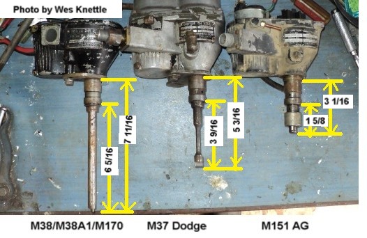
The M37 and M151 shafts are way to short.
Joined: Apr 08, 2009 Posts: 249 Location: Mariposa, Ca.
Posted: Sat Apr 06, 2013 3:37 pm Post subject:
The measurements for the A1 are similar to mine so the shaft is likely okay. Now that I looked at the manual I can see how the rotor can be 180 degrees off. I will look more closely at this possibility now with mine.
Thank you for the link and the measurements. I have some items to check now.
I found a used distributor on ebay for 100 bucks that is minus the plate but no way to determine if the cam is any good.
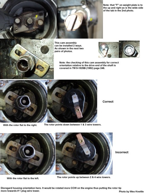
Apples & oranges Bill. The 180 we are discussing is the relative position of the cam assembly to the drive end of the shaft since they can be assembled to each other two ways which are 180 degrees apart.
We are not discussing 180 degrees out on timing or actually what you mean are wires 180 out of sequence on the cap. This distributor will only go into the pump drive one way. Unlike a small block Chevy which can be installed two ways and actually be timed 180 degrees off. In most improper oil pump indexings with the Willys 4 banger we end up clocking the wires one way or the other one hole which comes out to about 90 degrees of rotation of the wires relative to the cap and the housing can usually still swing enough to set timing close. If you move the wires 180 degrees or two holes in either direction you end up with a distributor housing that hits the block before you can get the timing right. _________________ Wes K
45 MB, 51 M38, 54 M37, 66 M101A1, 60 CJ5, 76 DJ5D, 47Bantam T3-C & 5? M100
Joined: Apr 17, 2005 Posts: 891 Location: New Hampshire
Posted: Sat Apr 06, 2013 6:06 pm Post subject:
I am aware that it will only go in one way. I am talking about the cam lobe (the part the makes the points open and close) being 180 degree out. The dist I put in my jeep is that way so mine does not match the manual at this time. No reason to change it as it runs just fine that way.
Joined: Apr 08, 2009 Posts: 249 Location: Mariposa, Ca.
Posted: Sat Apr 06, 2013 6:55 pm Post subject:
I got the dist. back in and hooked up to the shaft. When I tightened the pump bolts it engages as before. As in "just barely" I put a wide setting on the points so I could try to start the engine while waiting for whatever part I get to replace the bad cam lobes. Probably about .015 on the bad lobes and .035 on the good ones but I need to find out if I have any other problems to address. Still hoping to get to Camp Delta.
Thanks to all for the input and I will update this post with what find as a solution.
Joined: Apr 08, 2009 Posts: 249 Location: Mariposa, Ca.
Posted: Thu Apr 11, 2013 9:34 am Post subject:
I am updating this post because of what I have found on multiple distributors and the clocking issue of the oil pump and the distributor. I am really confused between what the manual says and what the dist. shows so maybe Wes can help me clean the cobwebs out of my head. I updated my oil pressure problem post and mentioned that I found a bent distributor shaft and ordered a rebuilt dist.
First, I found my dist was, as suspected, set up with the cam lobes 180 degrees off. But all three dist. that I looked at have the same shaft and when you hold the shaft in the position that it would be seated in the oil pump (1100), the rotor is pointing at #3, not #1 (1700). This is with the engine at top dead center. To get the rotor to #1, I have to put the oil pump position at 0100. Rotate the shaft 180 degrees and you have the same thing with only the thicker side of the shaft in a different position.
I noticed on a borrowed dist. the last person had set it up with the #1 wire in the #4 position, indicating to me that it was 180 off. The only thing I have not seen with my own eyes are the timing marks but I can't imagine that would have anything to do with the clocking on the pump in relation to the distributor question. I do understand it could affect the running of the engine. What am I missing? The manual was wrong on the #1 position. Is it also wrong on the oil pump position? _________________ Mike Wenrich
1961 USMC M38A1, 1965 M416B1 Trailer, 1956 Willys Wagon (Modified)
This post has become very long and very diverse. I have mentioned several things above that may or may not apply to your last post above. I even suggested above that you start at the beginning with the absolute basics.
Quote:
Posted: Sat Apr 06, 2013 11:23 pm Post subject:
To get us both on the same page lets start over.
1-Have you confirmed #1 is TDC on compression and the proper alignment of timing marks is set? (Note: Indexing pump and distributor is done with the #1 piston TDC not in the 5 deg. advanced firing position)
2-Have you confirmed the oil pump is the correct L & F134 pump and is installed correctly, with the correct thickness gasket (almost paper thin) and the correct indexing?
3-Does your distributor cam rotor flat align parallel with two of the cam flats? This is to confirm you have the correct cam on your distributor and has nothing to do with distributor indexing nor does the illustration have anything to do with distributor indexing.
and
Quote:
With #1 piston TDC on compression stroke and the timing gear marks aligned on the cam and crank gears. If you don't want to pull the crank pulley and timing cover then adapt a dial indicator to the #1 spark plug hole and measure to find the piston at TDC. Remember there's a short flat spot in crank rotation where the piston does not move up or down for about 3 to 5 degrees. You slowly bring the piston up untill there no more increase on the dial indicator and stop. Make a crayon mark on the crank pully that aligns with your timing pointer. Now very slowly continue rotating the crank in the same direction until the instant the dial indicator starts to decrease it's reading and stop. Make a second crayon mark on the crank pulley in line with your timing pointer. Now make a mark halfway between the two crayon marks (small circumference section of the pulley). Now erase the first two marks. Set your new TDC mark in alignment with your timing pointer. Make a permanent notch in the pulley. This is your TDC. Now use a degree wheel to back the crank pulley up 5 degrees and make your ignition timing notch in your pulley. Voila you now have permanent reliable timing marks.
Now go back to the book and set the pump in it's correct index position.
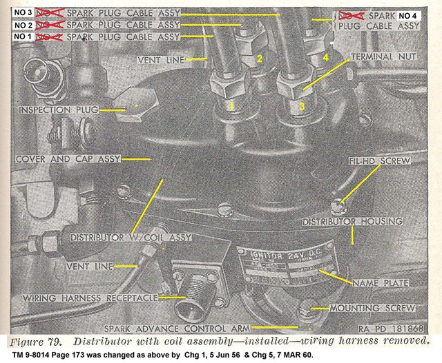
Now before you try to guess the correc t position of #1 plug wire on your distributor I caution you to read the two changes to TM 9-8014 that warn you the original illustration in your TM 9-8014 is incorrect and they give you the correct position in the two changes. I am talking about figure 79 on page 173. That figure is WRONG.
Now with your latest post when you describe a plug wire position which position are you quoting? The old incorrect wire arrangement or the new correct wire arrangement.?
When you say the three shafts are the same are all three in the correct cam to shaft relationship with the "F" on the shaft top plate aligned with the wide side of the shaft drive tab? _________________ Wes K
45 MB, 51 M38, 54 M37, 66 M101A1, 60 CJ5, 76 DJ5D, 47Bantam T3-C & 5? M100
Joined: Apr 08, 2009 Posts: 249 Location: Mariposa, Ca.
Posted: Thu Apr 11, 2013 1:39 pm Post subject:
Since I will be receiving a rebuilt dist. I decided to correct everything so I am working on a new clocking position. On page one I already answered that I confirmed everything you suggested. I have not been able to see the timing marks but I have determined TDC. I am at TDC but have not backed it off 5 degrees.
Your picture above shows cam positions and states that you can align with the rotor pointing correctly between the 2 and 4 position. According to the yellow lines on the corrected drawing, those are not in line with each other. They are next to each other.
The part the engages the oil pump is in the same alignment with the flat on the cam on all three shafts I have so if you install the rotor as pictured, it is pointing straight down. Now move the rotor to the left to point at #1 and the shaft and rotor are at 1 & 7 o'clock. For further reference I am using the lower left of the dist, and rotor pointing at the position near the electrical connection, marked No 1 in your picture. If that is the case I do not see how the shaft can be indexed as the manual suggests.
Also, you mention two corrections to the manual but referenced one of them. What is the other? And I know it's long and diverse but I am slow and thick. Sorry 'bout that. _________________ Mike Wenrich
1961 USMC M38A1, 1965 M416B1 Trailer, 1956 Willys Wagon (Modified)
On page one I already answered that I confirmed everything you suggested. I have not been able to see the timing marks but I have determined TDC. I am at TDC but have not backed it off 5 degrees.
Must be on the compression stroke. As I pointed out the only way to be exactly at TDC on compression is to have the timing marks or have the front cover off and see the crank gear vs cam gear alignment marks or use a dial indicator on the piston and do the split in the middle for the TDC flat spot where the crank moves about 5 to 8 degrees with no movement in the piston.
Quote:
Your picture above shows cam positions and states that you can align with the rotor pointing correctly between the 2 and 4 position. According to the yellow lines on the corrected drawing, those are not in line with each other. They are next to each other.
Not true. My photo states rotor pointing down between 1 & 3 is correct. That entire photo is designed to explain that you must have the cam installed correctly by placing the slot in the cam with the "LA" stamped on it over the pin on the shaft's weight mounting plate with the "F" stamped next to it. If you have verified this and you clock the pump according to the manual illustration the rotor will point down towards the 1 & 3 plug wires. This is a very general indication of direction of the rotor since you can swing the distributor housing nearly 100 degrees the rotor may actually be pointing at #1 or #3 wire or right in the middle. The point here is the rotor points downward.
Quote:
The part the engages the oil pump is in the same alignment with the flat on the cam on all three shafts I have so if you install the rotor as pictured, it is pointing straight down. Now move the rotor to the left to point at #1 and the shaft and rotor are at 1 & 7 o'clock. For further reference I am using the lower left of the dist, and rotor pointing at the position near the electrical connection, marked No 1 in your picture. If that is the case I do not see how the shaft can be indexed as the manual suggests.
Again as I just said above the direction is relative to the housing's position which can be wherever you last pushed it. The point is still that the rotor will be pointing downward. Somewhere near #1 & #3 wire towers. Later when you set the points you will be very close with the housing position adjustment to #1. This is because the next step is setting the points to .020 on the high point of the cam then swinging the housing so the rotor goes towards #1 wire tower until the points close. Then rotate slowly until the points just open and you are At the 5 degree BTDC firing point and the rotor is on #1 plug wire tower. Again the point here is pointing down somewhere between 0900 and 0300 on the bottom half of the clock is as close as you need to be when initially indexing the oil pump and then the distributor to the oil pump. You will usually not get real close to the rotor pointing at #1 wire until you move on to setting the points and static timing.
Quote:
Also, you mention two corrections to the manual but referenced one of them. What is the other?
Actually I said two changes not corrections. Changes are published sets of pages that update a manual. They contain additions and corrections. TM 9-8014 Change 1 dated June 1956 included the wiring correction and TM 9-8014 change 5 dated March 1960 included the wiring correction. One correction listed in two separate changes. _________________ Wes K
45 MB, 51 M38, 54 M37, 66 M101A1, 60 CJ5, 76 DJ5D, 47Bantam T3-C & 5? M100
Joined: Apr 08, 2009 Posts: 249 Location: Mariposa, Ca.
Posted: Fri Apr 12, 2013 9:26 am Post subject:
Okay. This makes sense to me now that I know the initial setting is placing the rotor in the ballpark but not directly on No. 1. I have been doing all this knowing I was on the compression stroke, using the middle of the flat spot. The 100 degree swing of the distributor does make up for a lot of initial rotor positioning. Right now, I have my oil pump setting to allow the rotor to point at No 1 which also allows the dist. to sit more parallel to the engine. I assumed that was what was intended by the designers.
Working before, on V-8 engines, that was always the way you set them up. Install the rotor pointing at the No.1 terminal.
The manual makes it sound so exacting that I did not realize the wiggle room built in. I know that you can use any terminal for No.1 if the firing order and wiring and TDC are correct and you place the rotor in the No.1 position. Again, I wanted to set this up the way it was intended. And your explanation that the rotor points down between the 1 & 3 wires is clear enough. I guess I read what I wanted to in that regard and thought you meant pointing at those towers. Thanks for making this understandable for me.
Now, I will drop and give you twenty Wes. _________________ Mike Wenrich
1961 USMC M38A1, 1965 M416B1 Trailer, 1956 Willys Wagon (Modified)
No need for the twenty Mike. Have a beer and remember Wes had to learn this also at some point many years ago!
The wag room is for the indexing of the pump. On most of those V8's the distributor was driven directly by the cam and the pump was driven by the distributor hence set rotor direct at #1 and make the pump line up with the distributor tang. Different ball game entirely. _________________ Wes K
45 MB, 51 M38, 54 M37, 66 M101A1, 60 CJ5, 76 DJ5D, 47Bantam T3-C & 5? M100
All times are GMT - 6 Hours Goto page Previous1, 2
Page 2 of 2
You cannot post new topics in this forum You cannot reply to topics in this forum You cannot edit your posts in this forum You cannot delete your posts in this forum You cannot vote in polls in this forum