Hi, I have the above unit in my Jeep with a PP-112/GR power supply mounted onto a MT-299/GR mount. For good weight distribution its behind the passenger seat.
The power supply lead is CX-2031A/U 8FT 3IN.
I have recently bought and mounted the Radio Receptical mounted by the side of the passenger seat. Mid West also supplied the male plug to fit into the Receptical from the Transmitter.
At the moment the power supply has a loop on the end of the positive ready to go onto a battery, the earth is just an open wire.
I have looked at many photos of these Transmitters power supply and that is how they are shown with the loop end on the terminals not connected into the Receptical.
I am correct in my thinking that the wiring should be soldered into the male connector and then into the Radio receptical, just the two wires each side?
I take it the loop end set up would be for just adding a power supply not using the Jeep batteries?
This is a whole new ball game to me as I only did a bit of Sideband on the C.B radios back in the 80ies. I do remember not to key the handset with no ariel connected.
Any thoughts would be appreciated.
Thanks.
Horse.
Receiver- Transmitter RT-68/GRC
-
horse

- Active Member

- Posts: 218
- Joined: Sat Sep 07, 2019 6:00 pm
- Location: Yorkshire U.K.
Receiver- Transmitter RT-68/GRC
1952 M38
-
wesk

- Site Administrator

- Posts: 16461
- Joined: Sun Apr 03, 2005 6:00 pm
- Location: Wisconsin
- Contact:
Using the US Army Signal Corp Installation Drawing for the AN/VRC-10 setup the PS cable end at the right seat receptacle is installed to the male connector. Those connectors were set up for crimp type pins. You can use solder if you like but it's not a requirement.
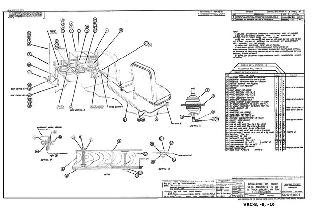
Here's the link to the full size file copy of this drawing: http://www.willysmjeeps.com/v2/modules. ... _photo.php
Here's the rear seat installation for the AN/VRC-10:
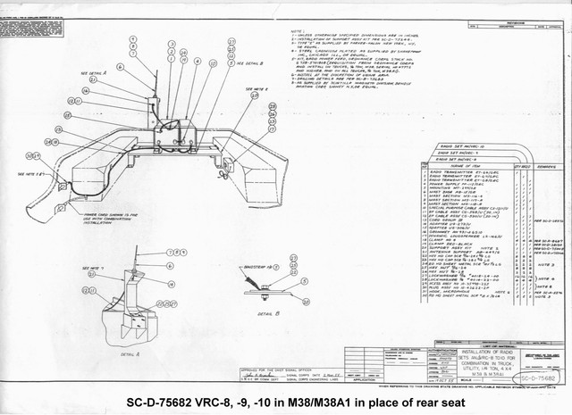
Here's a link to the full size file for this photo: http://willysmjeeps.com/v2/modules/gall ... 10_aft.jpg
The male PS plug and the female PS receptacle at the pass seat have the details for installing their pins in TM 9-1825E Bendix/Scintilla electrical product maintenance manual.
Here's the crimper:
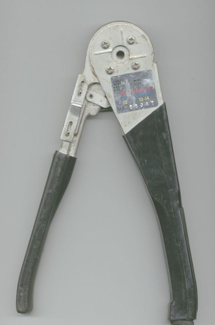
Here's the pin remover/setters:
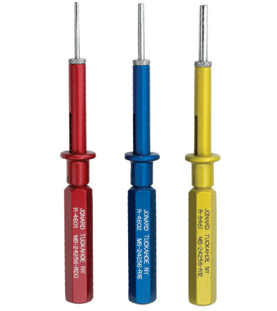
Here's the manual:
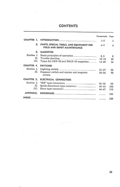
Chapter 5 is Bendix connectors:
Here's the link to the full size file copy of this drawing: http://www.willysmjeeps.com/v2/modules. ... _photo.php
Here's the rear seat installation for the AN/VRC-10:
Here's a link to the full size file for this photo: http://willysmjeeps.com/v2/modules/gall ... 10_aft.jpg
The male PS plug and the female PS receptacle at the pass seat have the details for installing their pins in TM 9-1825E Bendix/Scintilla electrical product maintenance manual.
Here's the crimper:
Here's the pin remover/setters:
Here's the manual:
Chapter 5 is Bendix connectors:
Wes K
45 MB, 51 M38, 54 M37, 66 M101A1, 60 CJ5, 76 DJ5D, 47Bantam T3-C & 5? M100
Mjeeps photo album: http://www.willysmjeeps.com/v2/modules. ... _album.php
45 MB, 51 M38, 54 M37, 66 M101A1, 60 CJ5, 76 DJ5D, 47Bantam T3-C & 5? M100
Mjeeps photo album: http://www.willysmjeeps.com/v2/modules. ... _album.php
-
horse
- Active Member
- Posts: 218
- Joined: Sat Sep 07, 2019 6:00 pm
- Location: Yorkshire U.K.
-
horse
- Active Member
- Posts: 218
- Joined: Sat Sep 07, 2019 6:00 pm
- Location: Yorkshire U.K.
-
horse
- Active Member
- Posts: 218
- Joined: Sat Sep 07, 2019 6:00 pm
- Location: Yorkshire U.K.
-
horse
- Active Member
- Posts: 218
- Joined: Sat Sep 07, 2019 6:00 pm
- Location: Yorkshire U.K.
-
RonD2
- Jeep Legend

- Posts: 2071
- Joined: Wed Oct 01, 2014 6:00 pm
- Location: South Carolina, Dorchester County
Hi Horse,horse wrote:For anybody doing this I found the A B C on the plug ends.
A = positive
B= Ground
C = I understand is a spare if any of the others go down in the field. Waiting for the correction on this.
Horse.
Which diagram in the radio set manual did you find the pin-out key that A = 24V and B = Ground?
Ron D.
1951 M38 Unknown Serial Number
1951 M100 Dunbar Kapple 01169903 dod 5-51
“The only good sports car that America ever made was the Jeep."
--- Enzo Ferrari
1951 M38 Unknown Serial Number
1951 M100 Dunbar Kapple 01169903 dod 5-51
“The only good sports car that America ever made was the Jeep."
--- Enzo Ferrari
-
wesk
- Site Administrator
- Posts: 16461
- Joined: Sun Apr 03, 2005 6:00 pm
- Location: Wisconsin
- Contact:
Most likely here:
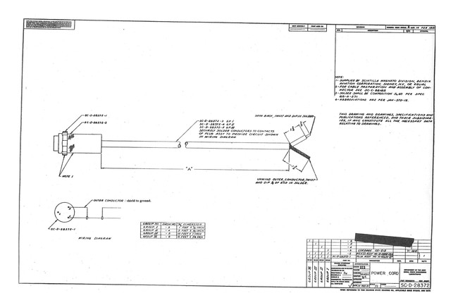
In the drawing in my previous post SC-D-28605 VRC 8-10 installation the cord in question item 16 lists the drawing number SC-D-28372 in the remarks column.
In the drawing in my previous post SC-D-28605 VRC 8-10 installation the cord in question item 16 lists the drawing number SC-D-28372 in the remarks column.
Wes K
45 MB, 51 M38, 54 M37, 66 M101A1, 60 CJ5, 76 DJ5D, 47Bantam T3-C & 5? M100
Mjeeps photo album: http://www.willysmjeeps.com/v2/modules. ... _album.php
45 MB, 51 M38, 54 M37, 66 M101A1, 60 CJ5, 76 DJ5D, 47Bantam T3-C & 5? M100
Mjeeps photo album: http://www.willysmjeeps.com/v2/modules. ... _album.php
-
horse
- Active Member
- Posts: 218
- Joined: Sat Sep 07, 2019 6:00 pm
- Location: Yorkshire U.K.
It would have been good if I had found the wiring diagram from Wes but I did not see that one.
The jeep is running well and I did not want to link up any power from the battery down to the Radio Receptical and cause other problems if I had got something wrong.
So with the Radio Receptical disconnected from the battery I put 12v down the positive lead from a separate battery to determine which was the live pin, which came out as A. There are only two wires on the radio power lead so that part was fine after checking nobody had switched the wires in the power unit.
Probably not the correct way of doing things but it got a result.
Horse.
Last edited by horse on Tue Jan 10, 2023 7:48 am, edited 3 times in total.
1952 M38
-
wesk
- Site Administrator
- Posts: 16461
- Joined: Sun Apr 03, 2005 6:00 pm
- Location: Wisconsin
- Contact:
Good job Horse! That must mean your radio power receptacle was wired already before you installed it coming with the two wires as an assembly.
Wes K
45 MB, 51 M38, 54 M37, 66 M101A1, 60 CJ5, 76 DJ5D, 47Bantam T3-C & 5? M100
Mjeeps photo album: http://www.willysmjeeps.com/v2/modules. ... _album.php
45 MB, 51 M38, 54 M37, 66 M101A1, 60 CJ5, 76 DJ5D, 47Bantam T3-C & 5? M100
Mjeeps photo album: http://www.willysmjeeps.com/v2/modules. ... _album.php
-
horse
- Active Member
- Posts: 218
- Joined: Sat Sep 07, 2019 6:00 pm
- Location: Yorkshire U.K.