| View previous topic :: View next topic |
| Author |
Message |
TonyMorreale
Member
Joined: Apr 16, 2005
Posts: 68
Location: Franklin, TN
|
 Posted: Sun Jan 22, 2006 6:07 pm Post subject: M38 instrument panel wire harness clip.. Posted: Sun Jan 22, 2006 6:07 pm Post subject: M38 instrument panel wire harness clip.. |
 |
|
Which wires are supposed to be secured with the harness clip on the back of the right side (when looking at the panel installed in the jeep) of the instrument cluster panel on the M38?
Also, on the back of the left side of the panel I have what appears to be a circuit breaker. I've got the 3 breakers on the battery box wired properly. Is this an extra breaker on the back of the instrument cluster panel?
I've got all the gauges wired up properly and was just checking on these two points before I go further....
_________________
Tony Morreale
Franklin, TN
|
|
| Back to top |
|
 |
Ryan_Miller
Site Administrator


Joined: Apr 03, 2005
Posts: 1634
Location: Kansas
|
| Posted: Sun Jan 22, 2006 9:36 pm Post subject: |
|
|
Yes,
There is supposed to be a circuit breaker on the backside of the gauge panel. This circuit breaker was discontinued in April 1952 at around vehicle SN MC65043.
There should be a spider harness on the back, there are several wire loom clips, one goes to that I believe.
Do you have photo of the clip to show the location?
_________________
Ryan Miller
MVPA # 22010 |
|
| Back to top |
|
|
wesk
Site Administrator

Joined: Apr 04, 2005
Posts: 16262
Location: Wisconsin
|
|
| Back to top |
|
|
Cacti_Ken
Member

Joined: Apr 20, 2005
Posts: 1021
Location: Silsbee, Texas
|
| Posted: Sun Jan 22, 2006 10:43 pm Post subject: |
|
|
I'm glad you explained that. I have the same instrument panel with the three circuit breaker bracket on the battery box also. So wire #11 from circuit breaker on battery box feeds ignition switch, then from ignition switch wire # 27 feeds breaker on instrument panel and then on to the gages. I had it wrong and thought the breaker on the inst. panel was one that I didn't need.
_________________
Tropical Veteran
35th Inf. Reg. "CACTI" 4th I.D. VN
Amateur Radio K5XOM |
|
| Back to top |
|
|
TonyMorreale
Member
Joined: Apr 16, 2005
Posts: 68
Location: Franklin, TN
|
| Posted: Sun Jan 22, 2006 10:57 pm Post subject: |
|
|
Thanks Wes. Glad I asked... I had #27 from the switch going directly to the spider harness. I'll re-route it through the breaker. Luckily I haven't put any juice through the system.
Since I'm using a solid state regulator and a Batt-Gen gauge the #8 & #9 wires would be unused making the spider harness the only connection to this gauge (since it's only got one connection) correct?
I'll take pics of the rear of the panel and try to post them tomorrow.
_________________
Tony Morreale
Franklin, TN
|
|
| Back to top |
|
|
Ryan_Miller
Site Administrator
Joined: Apr 03, 2005
Posts: 1634
Location: Kansas
|
| Posted: Mon Jan 23, 2006 11:58 am Post subject: |
|
|
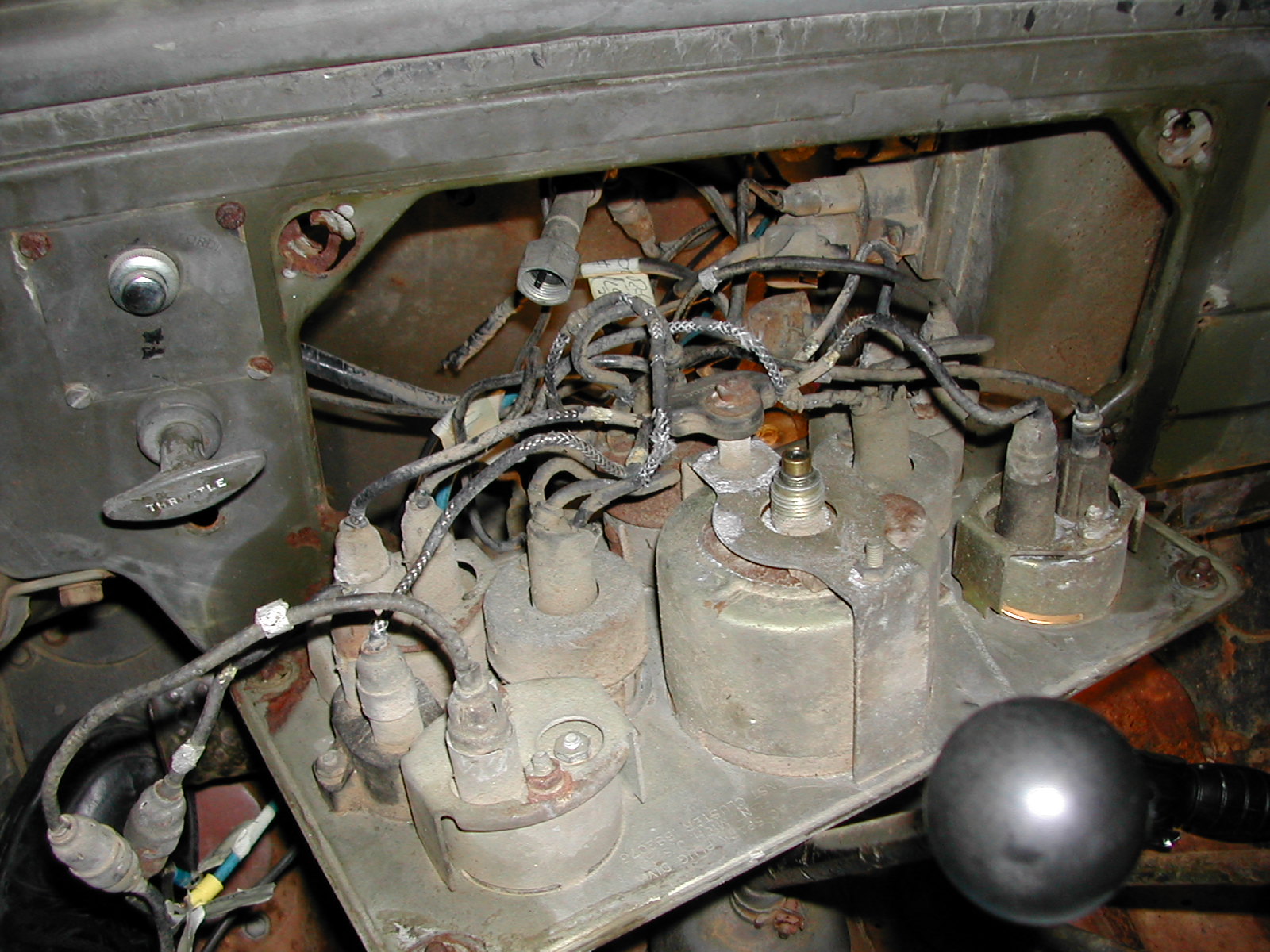
Tony,
Here is a shot of the dash wiring from a 51 M38, but it does not really show the wiring clips very well.
_________________
Ryan Miller
MVPA # 22010 |
|
| Back to top |
|
|
wesk
Site Administrator
Joined: Apr 04, 2005
Posts: 16262
Location: Wisconsin
|
|
| Back to top |
|
|
TonyMorreale
Member
Joined: Apr 16, 2005
Posts: 68
Location: Franklin, TN
|
| Posted: Mon Jan 23, 2006 8:03 pm Post subject: |
|
|
Now I'm confused, which is not unusual for me and this project.
What do the 95 Ohm connectors do and are they necessary? From what I can tell, my M38 didn't have any originally and the pic that Ryan posted above doesn't seem to show them either. Are they related to the use of a solid state regulator?
Wes, and Ryan, I'll email you pics of the rear of my instruments as I do not have a photo sharing page or a gallery at present in order to do the proper linking.
As always, your expertise and help are greatly appreciated...
_________________
Tony Morreale
Franklin, TN
|
|
| Back to top |
|
|
wesk
Site Administrator
Joined: Apr 04, 2005
Posts: 16262
Location: Wisconsin
|
|
| Back to top |
|
|
TonyMorreale
Member
Joined: Apr 16, 2005
Posts: 68
Location: Franklin, TN
|
| Posted: Mon Jan 23, 2006 8:43 pm Post subject: |
|
|
I didn't notice the message at the top as I was navigating the large scans. I can't get them to fit on screen and can only see them by scrolling left-right and up-down to try to take in the images. My dash plate is #56957 engine MC97051.
_________________
Tony Morreale
Franklin, TN
|
|
| Back to top |
|
|
Ryan_Miller
Site Administrator
Joined: Apr 03, 2005
Posts: 1634
Location: Kansas
|
| Posted: Mon Jan 23, 2006 9:01 pm Post subject: |
|
|
Tony,
There is more detail on those large scans.
You can condense thier size by saving them as a file and then
looking at them with a photo program.
The external resistor gauges were a very early M38 item.
They were not used on later M38 vehicles.
_________________
Ryan Miller
MVPA # 22010 |
|
| Back to top |
|
|
|

