Posted: Mon Nov 08, 2021 5:54 pm Post subject: M38 Voltage Regulator
M38 Voltage Regulator: Pandora's Box
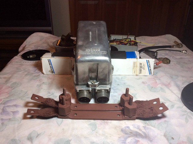
I am sure to have questions about the VR but thought a detailed dissection would be an enjoyable first step. My zoology degree from U of F (go Gators), several summers working in local slaughter plants, squirrel hunting with my grandfather along the back lane and decades of cutting up God's creatures in a HS biology lab prepared me for the dismantling of a M38. Putting things back together ..... not so much.
More pics later. Then some questions. _________________ Don Alvarez
Retired HS Teacher
Central Florida
M38 Project
did you have the regulator and generator tested together first before tearing it down? They have a remarkable ability to remain functional. sometimes just slight adjustments to get within specs.
autolite genertators and regulators were used on the m38 _________________ Gary Keating
1949 C3A, 1952 M38,
1954 M170, 1957 Cj3B
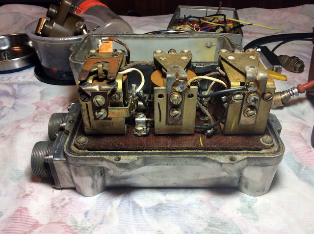
The VR and generator have not been tested. I can't find a shop in my area that works on military electrical system components so I opened th VR, looking for any obvious problems and will later follow the manual on some basic cleaning.
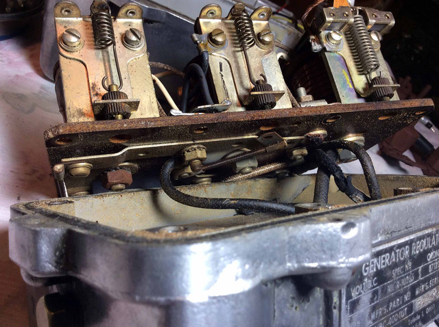
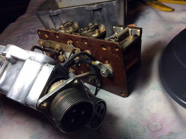
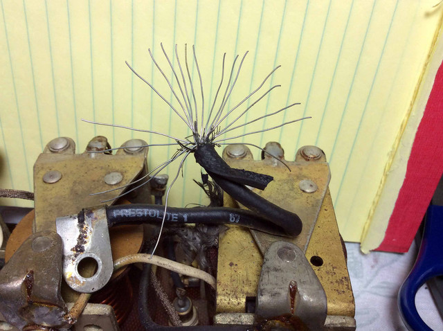
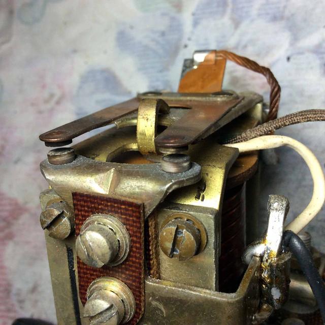
Here are more pics. There looks to have been a past wire meltdown.
_________________ Don Alvarez
Retired HS Teacher
Central Florida
M38 Project
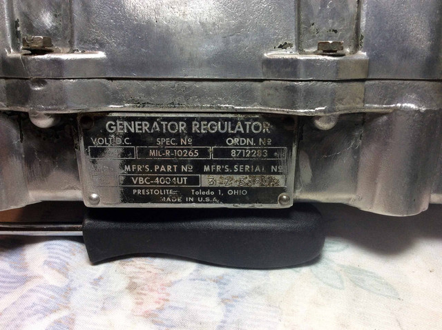
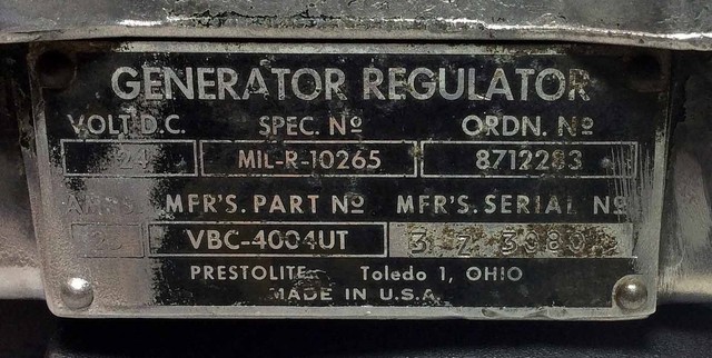
Ord 9 SNL G-740/ P. 100/ Fig. 06-3 shows the M38 'Generator Regulator'. Could a Prestolite VBC-4004UT ever have found its way onto this jeep while still in military service?
Are there any 'Motorpool Class' M38 restorations on the streets of America with a Prestolite VR tucked down beside a Auto-Lite GHA-4802BUT generator? _________________ Don Alvarez
Retired HS Teacher
Central Florida
M38 Project
I was always curious about the proper rebuilding of one of these and adjustment. The manuals go so far, but to have someone that actually worked on these and repaired/adjusted them would be interesting. _________________ Ryan Miller
MVPA # 22010
Joined: Oct 02, 2014 Posts: 1910 Location: South Carolina, Dorchester County
Posted: Wed Nov 10, 2021 5:34 pm Post subject:
If it helps, out of curiosity, I discovered that:
The September 1955 M38 ORD9 on page 133 only lists the VBC-4002UT (Ord# G741-7524309).
The June 1956 ORD7 Organizational Maintenance Allowances for the M38 lists 2 Autolite Generator Regulators, the VBC-4002UT (Ord G741-7524309) and the VBC-4003UT (Ord G742-8689216). It also lists 3 Delco-Remy Generator Regulators (all 3 with G742 Ord#s). The G741 is the M37 truck and the G742 is the M35 truck.
The November 1952 TM9-1825B Electrical Equipment (Autolite) only lists the VBC-4002UT, with very detailed servicing instructions. The VBC-4004UT photos that Don posted look very similar to it, but who knows for sure?
I wasnt able to verify that the VBC-4004UT is listed in the M37 and M35 manuals, or in a later date of the TM9-1825B (because I dont have and cant find those manuals). Only the VBC-4002 is listed in the M38A1 ORD9.
Given the Army Supply System propensity for updating and superseding parts as vehicles age over their lifespan, it seems quite possible, even likely, that the VBC-4004UT (Ord# 8712283) is correct for the M38, but it isnt reflected in the manuals that I could find.
Im thinking Wes needs to weigh in on the VBC-4004UT. _________________ Ron D.
1951 M38 Unknown Serial Number
1951 M100 Dunbar Kapple 01169903 dod 5-51
The only good sports car that America ever made was the Jeep."
--- Enzo Ferrari
Last edited by RonD2 on Wed Nov 10, 2021 6:33 pm; edited 2 times in total
to have someone that actually worked on these and repaired/adjusted them would be interesting. Ryan
I was about to say, Im your huckleberry but that would be an over the top accomplishment for a New-be. I do intend to tackle some obvious stuff and go as far as prudence allows.
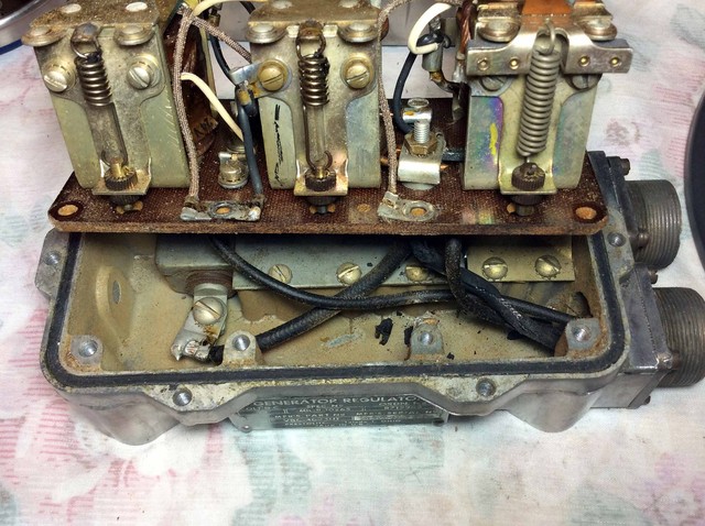
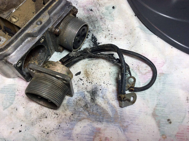
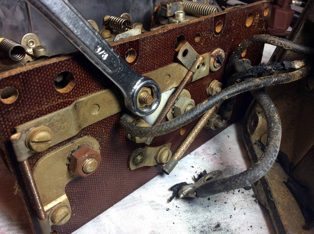
* So first lets take a look at those fried wires. (See above pics)
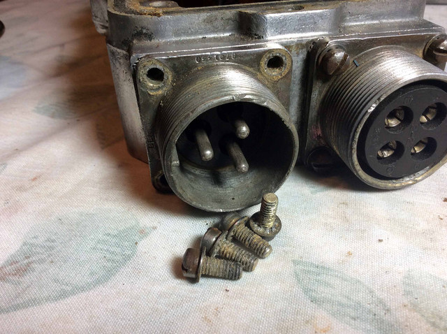
The manual describes a lengthy process that involves removing the three pins and grommet..... but is that really necessary? Its just three burned wires. The plug looks OK. So.
How about removing the terminal ends of the fried wires and use them to replicate the wiring pattern at that end (14 gauge wire ???)
How about leaving the pins in the grommet and clip the bad wires flush with each pin.... maybe nibble out the grommet at the base of each pin which would give more bite surface for a wire to pin terminal. (DIY/whatever)
Follow the original pin/wire configuration as you clamp or solder the wires and pins into your special terminal at the plug/pin end.
You would/ should end up with a refurbished sub-harness component.
If this sounds reasonable I will do it and move on to other VR concerns. _________________ Don Alvarez
Retired HS Teacher
Central Florida
M38 Project
Joined: Oct 02, 2014 Posts: 1910 Location: South Carolina, Dorchester County
Posted: Wed Nov 10, 2021 5:50 pm Post subject:
Sounds ok to me, except wondering what might have caused those "fried" wires?
Do you know the VR was working the last time it was used?
I'd suggest making careful note of which wires are fried --- because that information might (or might not) lead to other problem(s).
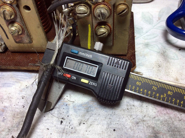
The ORD9 exploded diagram and parts list (for the VBC-4002UT) gives no clue about wire gauge size that I could find. Off-hand, I'd guess that 14 gauge might be too light for 28volt 25 amps. Perhaps 12 or even 10 gauge instead. About all you could do is carefully measure (after removing insulation) the diameter of the wire and count the number of strands to get a clue. _________________ Ron D.
1951 M38 Unknown Serial Number
1951 M100 Dunbar Kapple 01169903 dod 5-51
The only good sports car that America ever made was the Jeep."
--- Enzo Ferrari
Definitely need to know why the wires burned up - was there a resistor fried or a stuck spring, etc.
That is where a repair/tune up manual would be great, but I would bet these units were either replaced or rebuilt by the manufacturer or a subcontractor. _________________ Ryan Miller
MVPA # 22010
All good info. I wil more closely examine/measure the wires and look for any obvious cause of the meltdown.
The engine was partly disassembled when I bought the jeep so I never saw it running. _________________ Don Alvarez
Retired HS Teacher
Central Florida
M38 Project
1 - to have someone that actually worked on these and repaired/adjusted them would be interesting. Ryan
I was about to say, Im your huckleberry but that would be an over the top accomplishment for a New-be. I do intend to tackle some obvious stuff and go as far as prudence allows.
* So first lets take a look at those fried wires. (See above pics)
2 - The manual describes a lengthy process that involves removing the three pins and grommet..... but is that really necessary? Its just three burned wires. The plug looks OK. So.
1 - I have worked on these regulators since my first 24V M38A1 I purchased in 1986. I worked on their predecessor used in the MB's GPW's since 1971 in my GPW. The important things to make sure you do not get into trouble are:
A - Use the correct manuals. Beg, borrow or steal them but you will not be very successful at repairing/adjusting these heavy voltage regulators without them. In this case TM 9-1825B 1952 Ed., TM 9-1825E 1952 Ed., and the operator's and parts manuals for the applicable vehicle.
B - REMOVE BATTERY CABLE DURING YOUR REPAIR ATTEMPTS. This is especially important during the acts of removing and installing the metal lid. A simple clumsy moment with 24V's can leave you running from the smoke and having one helluva repair bill!!! Only connect the cable when the manual tells you too.
C - The early Prestolite/Autolite civilian service manuals have a ton of info concerning these regulators and they also published excellent training guides so keep your eyes open.
D - There are several very good basic electrical training guides on the shelf. There are super Autolite/Prestolite guides manuals available quite reasonable if you'll just set down and quiz google for a few minutes.
2 - Lesson one in electrical repair. The more you interrupt an electrical wire the poorer it will perform and the more often it will give you grief. Electrical connectors or Cannon Plugs as their usually called are handy devices and if you learn the HOW TO first the doing it becomes easy and quick. It seldom takes me more than 5 or 10 minutes to re-pin a 3 pin cannon plug with the correct tools in front of me. Most of these plugs use either crimp style pins or solder pins. Usually your choice. Remember that selecting a specific wire gauge is the end of the selecting process. The selecting process starts with the wire's environment, materials, run length, allowable voltage drop, and effects of amperage carrying on heat buildup. There are many manuals available dedicated to wire selection entirely. Again, take a moment and let your fingers do the walking. If you haven't noticed yet TM 9-1825E addresses re-pinning these plugs and you can find wire charts in my photo albums.
Try not using the word "MILITARY" when describing your electrical devices to a prospective repair shop. You'd be surprised at how much they really already know about these regulators but many shops just view them as time consuming due to their waterproof construction and special military requirements and thus not that profitable to them. I can assure you they have seen plenty of 24V equipment in big vehicles and emergency vehicles.
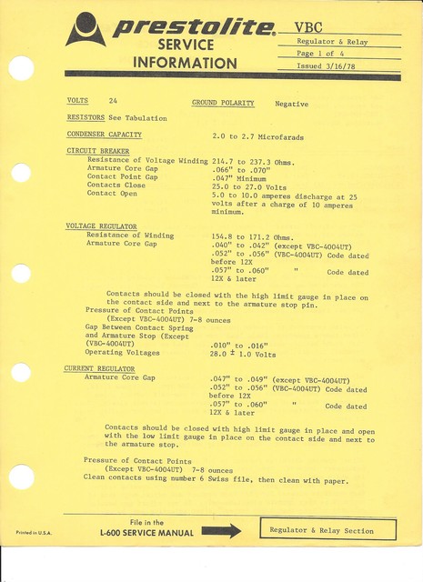
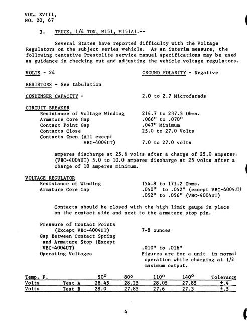
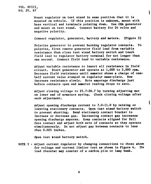
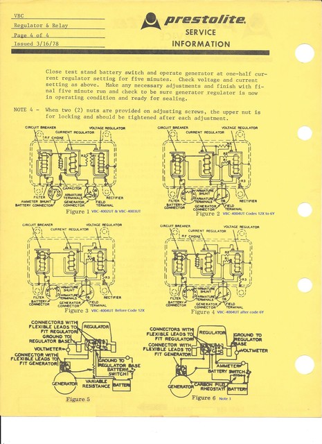
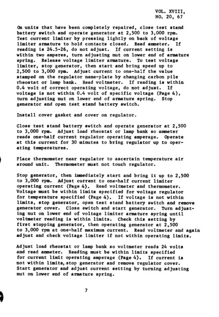
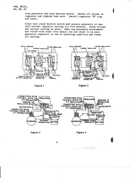
Now I have a tremendous amount of data and pubs available to me but I am still unable to find a documents substitution allowance for the VBC-4004UT to replace the VBC-4002UT and VBC-4003UT regulators. If you review my civilian Prestolite Manual exerpts below you can see that the 4004 differs considerably from the the other two.
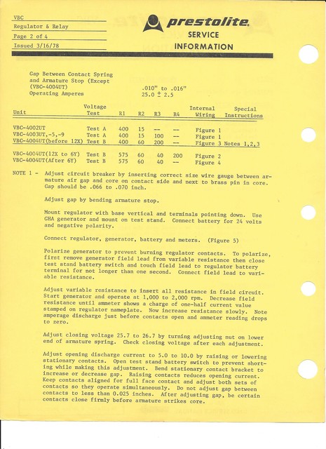
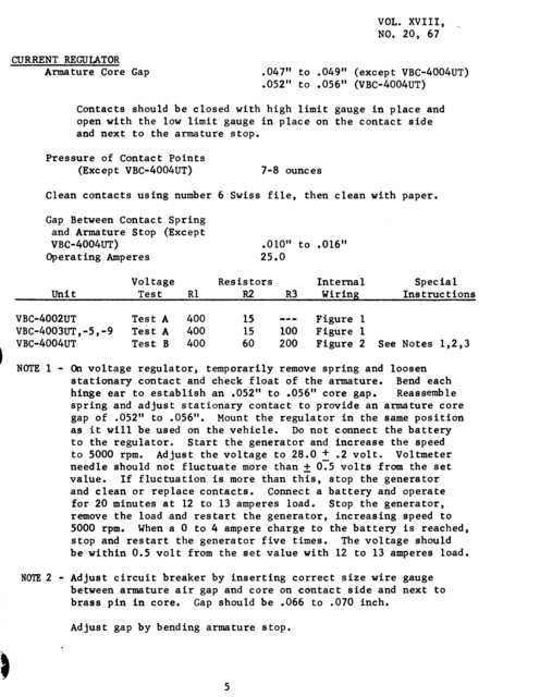
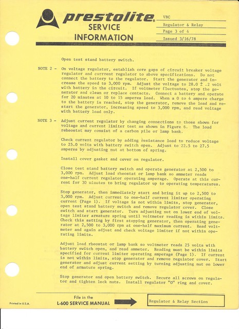
A quick comparison of the white page early 1967 preliminary Prestolite spec sheet with the 11 years later yellow page 1978 edition should make it obvious the superseding 1978 edition should be used today.
Don, What is the Amp rating on the left side of your regulator's ID plate? Disregard, I chopped it out of your original photo and got it large enough to read:
That 3Z serial puts your regulatory as listed on page 2 of the Prestolite spec sheet in the 12X to 6Y group.
I will pick out the info relevant to my VBC-4004UT VR from the Prestolite Service Info Sheet so as to identify the proper specs. I may also go back to the auto electric shop, manuals in hand, and have another talk.
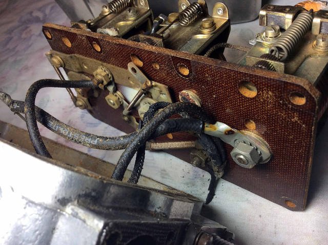
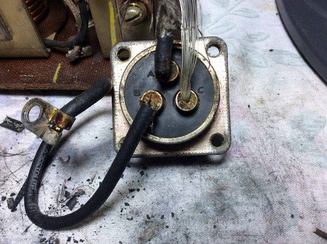
Here are some other pics of the wiring.
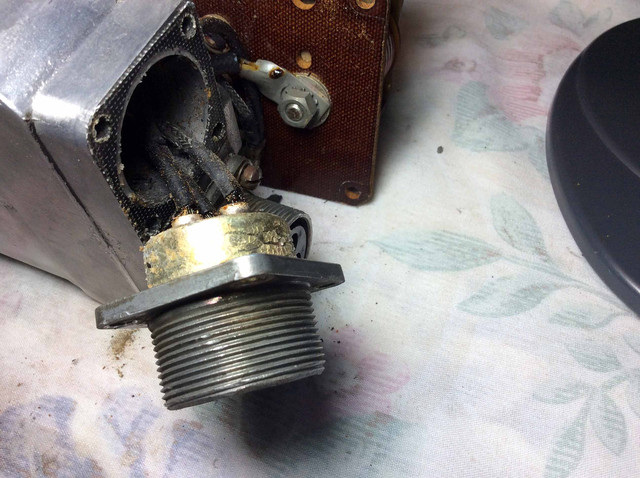
Wires at pins A & C merge to a common terminal end.
Pin B has a single wire.
The old twisted wire has about twenty strands and is about .07" in diameter. I have some new 12 gauge stranded wire that is rated at 40AMP for lengths under a meter and is about the same diameter but has about 45 strands.
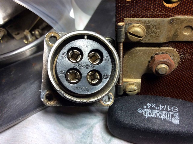
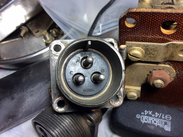
Here are two of the four points.
Cannon Plugs
_________________ Don Alvarez
Retired HS Teacher
Central Florida
M38 Project
Last edited by Naugha on Fri Nov 12, 2021 5:33 am; edited 2 times in total
Joined: Oct 02, 2014 Posts: 1910 Location: South Carolina, Dorchester County
Posted: Thu Nov 11, 2021 5:24 pm Post subject:
Don,
As Brian mentioned above, in a couple of your photos the word "Prestolite" can be seen printed on the wire insulation. Are there any numbers also imprinted? The wire gauge would be one of them if you can read it.
Your measurement and strand count on that particular wire seems to indicate 14 gauge. You can google a stranded wire gauge dimension table. And all the wire might not be the same gauge.
Don't know if you have the VR entirely disassembled yet, but have you found any other parts that look like they "fried"? Wire is easy enough to replace. Anything else might be difficult to find and buy. Can you trace the burnt wire(s) to their internal components?
I hope you can find an old-school auto-electric shop. I had a gentleman in Georgia rebuild my starter. He had the parts. Not cheap, but not much other choice. _________________ Ron D.
1951 M38 Unknown Serial Number
1951 M100 Dunbar Kapple 01169903 dod 5-51
The only good sports car that America ever made was the Jeep."
--- Enzo Ferrari
All times are GMT - 6 Hours Goto page 1, 2, 3, 4, 5Next
Page 1 of 5
You cannot post new topics in this forum You cannot reply to topics in this forum You cannot edit your posts in this forum You cannot delete your posts in this forum You cannot vote in polls in this forum