
Trying to troubleshoot two of my gages.
For the oil pressure gage, with the wire disconnected, the side going to the sending unit should be isolated and not be grounded through the case, correct?
The water temp gage has 24 volts reaching it, had a good wire to the sending unit, but fails to perform like the troubleshooting guide says. Is there another test I can perform on it?
Oil PRESS Gage
-
brachus12
- Member
- Posts: 40
- Joined: Sun Aug 14, 2011 6:00 pm
- Location: Upstate SC
- Contact:
Oil PRESS Gage
47 CJ2A "Bugger"
42 Ford GPW
62 Willys M170
42 Ford GPW
62 Willys M170
-
wesk

- Site Administrator

- Posts: 16469
- Joined: Sun Apr 03, 2005 6:00 pm
- Location: Wisconsin
- Contact:
Don't shotgun troubleshoot your gauge systems. Use the tech bulletin that walks you through it step by step, answers all your questions and gives you all the specs without loosing any accuracy in the transmission across the internet.
Army TB 9-2300-228-20 Tactical Transport and Combat Vehicles: Troubleshooting for Instrument Cluster Gages, Switches, Circuit Breakers, Sending Units and Related Wiring dated 8 July 1960.
http://www.cj3a.info/sibling/milgauge/milgage.htm
Army TB 9-2300-228-20 Tactical Transport and Combat Vehicles: Troubleshooting for Instrument Cluster Gages, Switches, Circuit Breakers, Sending Units and Related Wiring dated 8 July 1960.
http://www.cj3a.info/sibling/milgauge/milgage.htm
Wes K
45 MB, 51 M38, 54 M37, 66 M101A1, 60 CJ5, 76 DJ5D, 47Bantam T3-C & 5? M100
Mjeeps photo album: http://www.willysmjeeps.com/v2/modules. ... _album.php
45 MB, 51 M38, 54 M37, 66 M101A1, 60 CJ5, 76 DJ5D, 47Bantam T3-C & 5? M100
Mjeeps photo album: http://www.willysmjeeps.com/v2/modules. ... _album.php
-
brachus12
- Member
- Posts: 40
- Joined: Sun Aug 14, 2011 6:00 pm
- Location: Upstate SC
- Contact:
Sorry, my post was a bit incomplete.
I was working through the gage troubleshooting manual.
After the oil press gage kept failing each test, I finally checked the ports on back with no cables attached.
Using a multimeter, the one that would go to the sending unit appeared to be grounded through the case.
I was asking if that connection shouldn't be isolated from the case?
I was working through the gage troubleshooting manual.
After the oil press gage kept failing each test, I finally checked the ports on back with no cables attached.
Using a multimeter, the one that would go to the sending unit appeared to be grounded through the case.
I was asking if that connection shouldn't be isolated from the case?
-
wesk
- Site Administrator
- Posts: 16469
- Joined: Sun Apr 03, 2005 6:00 pm
- Location: Wisconsin
- Contact:
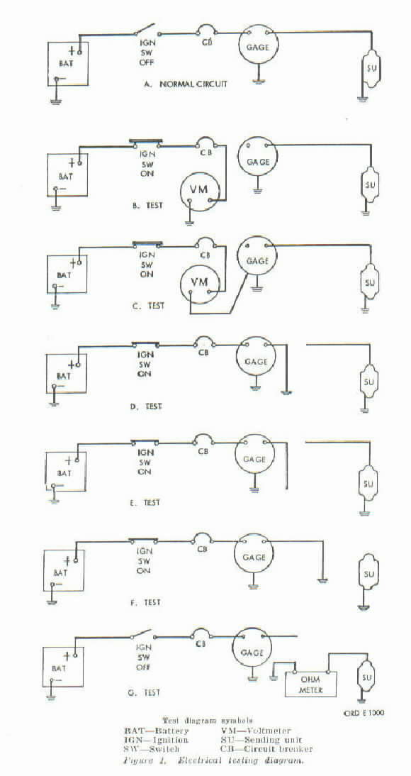
The gauges all have two grounds. One thru the case and one thru the sender. If you remove the lead from the sender and connect the ohm meter to it and touch the other test lead to the dash, frame. tub or gauge case you will show continuity if all is correct since both share the same ground. I assume you are doing test "G" and instead of touching the left probe in the illustration below to the vehicle's tub you are touching it to the gauge case. As you can see in the illustration both are grounded to the jeep. If on the otherhand you have the ohm meter connected to the gauge case and the gauge's sender terminal on the back of the gauge then you should not have continuity.
Wes K
45 MB, 51 M38, 54 M37, 66 M101A1, 60 CJ5, 76 DJ5D, 47Bantam T3-C & 5? M100
Mjeeps photo album: http://www.willysmjeeps.com/v2/modules. ... _album.php
45 MB, 51 M38, 54 M37, 66 M101A1, 60 CJ5, 76 DJ5D, 47Bantam T3-C & 5? M100
Mjeeps photo album: http://www.willysmjeeps.com/v2/modules. ... _album.php
-
brachus12
- Member
- Posts: 40
- Joined: Sun Aug 14, 2011 6:00 pm
- Location: Upstate SC
- Contact:
-
wesk
- Site Administrator
- Posts: 16469
- Joined: Sun Apr 03, 2005 6:00 pm
- Location: Wisconsin
- Contact:
The gauges are only serviceable through the rolled bezel on their face. There are tools made for uncrimping these bezels and then roll crimping them back on but there is no published data available for internal repair guidance. Their innards are extremely sensitive. At a price running in the $40 range it's hard to justify several hours of repair work.
Wes K
45 MB, 51 M38, 54 M37, 66 M101A1, 60 CJ5, 76 DJ5D, 47Bantam T3-C & 5? M100
Mjeeps photo album: http://www.willysmjeeps.com/v2/modules. ... _album.php
45 MB, 51 M38, 54 M37, 66 M101A1, 60 CJ5, 76 DJ5D, 47Bantam T3-C & 5? M100
Mjeeps photo album: http://www.willysmjeeps.com/v2/modules. ... _album.php