On page one I already answered that I confirmed everything you suggested. I have not been able to see the timing marks but I have determined TDC. I am at TDC but have not backed it off 5 degrees.
Must be on the compression stroke. As I pointed out the only way to be exactly at TDC on compression is to have the timing marks or have the front cover off and see the crank gear vs cam gear alignment marks or use a dial indicator on the piston and do the split in the middle for the TDC flat spot where the crank moves about 5 to 8 degrees with no movement in the piston.
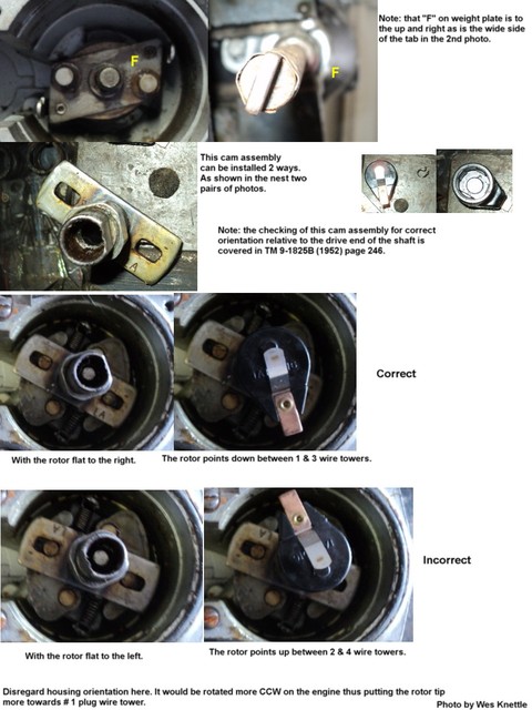
Your picture above shows cam positions and states that you can align with the rotor pointing correctly between the 2 and 4 position. According to the yellow lines on the corrected drawing, those are not in line with each other. They are next to each other.
Not true. My photo states rotor pointing down between 1 & 3 is correct. That entire photo is designed to explain that you must have the cam installed correctly by placing the slot in the cam with the "LA" stamped on it over the pin on the shaft's weight mounting plate with the "F" stamped next to it. If you have verified this and you clock the pump according to the manual illustration the rotor will point down towards the 1 & 3 plug wires. This is a very general indication of direction of the rotor since you can swing the distributor housing nearly 100 degrees the rotor may actually be pointing at #1 or #3 wire or right in the middle. The point here is the rotor points downward.
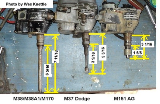
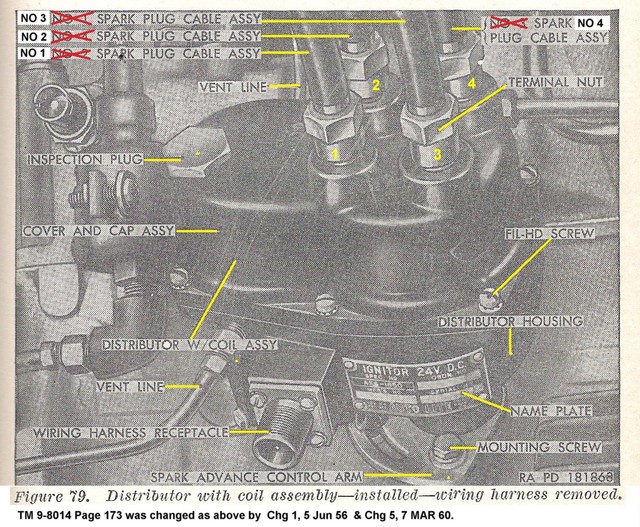
The part the engages the oil pump is in the same alignment with the flat on the cam on all three shafts I have so if you install the rotor as pictured, it is pointing straight down. Now move the rotor to the left to point at #1 and the shaft and rotor are at 1 & 7 o'clock. For further reference I am using the lower left of the dist, and rotor pointing at the position near the electrical connection, marked No 1 in your picture. If that is the case I do not see how the shaft can be indexed as the manual suggests.
Again as I just said above the direction is relative to the housing's position which can be wherever you last pushed it. The point is still that the rotor will be pointing downward. Somewhere near #1 & #3 wire towers. Later when you set the points you will be very close with the housing position adjustment to #1. This is because the next step is setting the points to .020 on the high point of the cam then swinging the housing so the rotor goes towards #1 wire tower until the points close. Then rotate slowly until the points just open and you are At the 5 degree BTDC firing point and the rotor is on #1 plug wire tower. Again the point here is pointing down somewhere between 0900 and 0300 on the bottom half of the clock is as close as you need to be when initially indexing the oil pump and then the distributor to the oil pump. You will usually not get real close to the rotor pointing at #1 wire until you move on to setting the points and static timing.
Also, you mention two corrections to the manual but referenced one of them. What is the other?
Actually I said two changes not corrections. Changes are published sets of pages that update a manual. They contain additions and corrections. TM 9-8014 Change 1 dated June 1956 included the wiring correction and TM 9-8014 change 5 dated March 1960 included the wiring correction. One correction listed in two separate changes.