I have a 1954 M38A1. Its been in my family since I was 14. I'm 50 now. 2 years ago I finally talked my dad into letting me have it. I have struggled with the ignition system since day 1. I didn't have a timing light when I started but I have one now. The timing on my engine is 25 degrees off. I cant advance the timing enough to hit the 5 degree mark. I was told I need to turn the gear on the oil pump clockwise by one tooth. Does anyone know of an easy and accurate way to do this? It runs ok now, can get up to speed but it has no pulling power or takeoff power and its sometimes difficult to start. It cuts off sometimes when I stop as well. All new components except for distributer housing. New plugs, wires, ignition coil, points.
I tried searching the forum but every search I enter gives no results found.
Oil Pump Gear/distributor timing
-
jaybrabble

- Member
- Posts: 19
- Joined: Fri Feb 24, 2017 6:00 pm
-
oilleaker1
- Jeep Enthusiast

- Posts: 973
- Joined: Wed May 13, 2009 6:00 pm
- Location: South Dakota
The distributor has a offset drive on it that matches the oil pump drive. To change one tooth either way, you have to pull the oil pump down out of the engine block and rotate it the direct it needs to go to accomplish this. The gear spirals up and fits into the worm drive cut gear in the camshaft. Then you re-match the offsets. Not a very easy job. You may rip the oil pump gasket also. Read your manual and look at the pictures beofre you do this. John
-
wesk

- Site Administrator

- Posts: 16462
- Joined: Sun Apr 03, 2005 6:00 pm
- Location: Wisconsin
- Contact:
Just go to my photo album under Ignition Timing:
http://www.willysmjeeps.com/v2/modules. ... _album.php
The basic point is to place the distributor in the block with #1 cylinder at top on compression at the 5 Deg BTDC position. Then position the rotor of the distributor so it is at the 0700 position as you face it (pointing towards the lower left as viewed from along the passenger side of the engine. A word of caution here, the illustration of the #1 rotor position in the TM 9-8014 in Fig 79 on page 173 is incorrect. Use the illustration in TM 8015-1 Fig 106 on page 141.
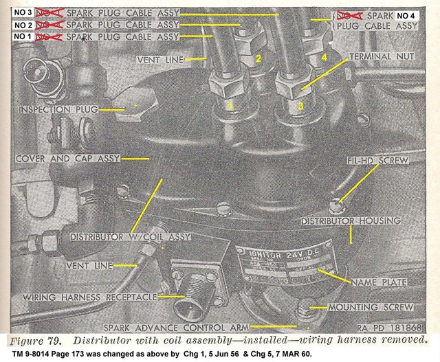
This is a correction of the Fig 79 from TM 9-8014
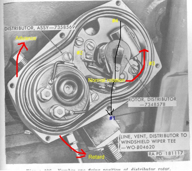
This is Fig 106 from TM 9-8015-1
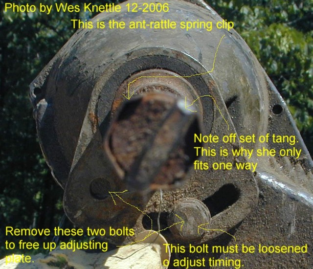
This illustrates the offset tab at the bottom of the distributor shaft that must interface with a corresponding offset in the oil pump drive end.
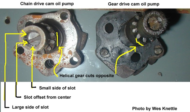
This is the top (drive end) of the oil pump.
Keep in mind that the gear on the camshaft drives the gear on the oil pump and the oil pump drives the distributor.
Other useful links:
http://willysmjeeps.com/downloads/Ignit ... .lines.pdf
Here's an old short set of instructions:
http://www.willysmjeeps.com/v2/modules. ... _album.php
The basic point is to place the distributor in the block with #1 cylinder at top on compression at the 5 Deg BTDC position. Then position the rotor of the distributor so it is at the 0700 position as you face it (pointing towards the lower left as viewed from along the passenger side of the engine. A word of caution here, the illustration of the #1 rotor position in the TM 9-8014 in Fig 79 on page 173 is incorrect. Use the illustration in TM 8015-1 Fig 106 on page 141.
This is a correction of the Fig 79 from TM 9-8014
This is Fig 106 from TM 9-8015-1
This illustrates the offset tab at the bottom of the distributor shaft that must interface with a corresponding offset in the oil pump drive end.
This is the top (drive end) of the oil pump.
Keep in mind that the gear on the camshaft drives the gear on the oil pump and the oil pump drives the distributor.
Other useful links:
http://willysmjeeps.com/downloads/Ignit ... .lines.pdf
Here's an old short set of instructions:
Here's a longer winded set:92. Install Oil Pump
Place a finger on No. 1 spark plug hole, and turn the crankshaft until No. 1 piston is (just starting to come up) coming up on compression stroke. Continue turning the crankshaft until the timing mark “5’” on the flywheel is alined with the index mark in the center of the timing hole on the engine rear plate (fig. 76) (or on late models when the pulley timing notch aligns with 5 degree mark on the timing cover tab.). Install the distributor in the cylinder block (par. 98)) temporarily. Set the rotor on No. 1 firing position (pointing about 7 o’clock) with the ignition points just breaking. Immerse the oil pump in a container of oil (same grade as used in the engine), and turn the inner rotor and shaft until the oil flows from the outlet hole in the oil pump housing. Place a gasket on the oil pump and, with the wide side of the slotted end of the shaft assembly up, install the oil pump on the engine, making sure the slot in the oil-pump shaft engages with the distributor shaft while the rotor is on No. 1 firing position with ignition points just breaking. Install the three yrs-inch cap screws that secure the oil pump to block. Remove distributor.
Oil Pump and Distributor Installation
TM 9-1804A M38 Engine & Clutch
92. Install Oil Pump
Place a finger on No. 1 spark plug hole, and turn the crankshaft until No. 1 piston is coming up on compression stroke. Continue turning the crankshaft until the timing mark “5’” on the flywheel is alined with the index mark in the center of the timing hole on the engine rear plate (fig. 76). Install the distributor in the cylinder block (par. 98)) temporarily. Set the rotor on No. 1 firing position with the ignition points just breaking. Immerse the oil pump in a container of oil (same grade as used in the engine), and turn the inner rotor and shaft until the oil flows from the outlet hole in the oil pump housing. Place a gasket on the oil pump and, with the wide side of the slotted end of the shaft assembly up, install the oil pump on the engine, making sure the slot in the oil-pump shaft engages with the distributor shaft while the rotor is on No. 1 firing position with
ignition points just breaking. Install the three yrs-inch cap screws that secure the oil pump to block. Remove distributor.
98. Install Distributor (fig. 33)
Place a thumb over No. 1 spark plug hole, and turn the crankshaft until No. 1 piston is coming up on compression stroke, and the timing mark “5”” on the flywheel is alined with the index line on the engine rear plate. Install the distributor on the engine, and rotate the rotor until the distributor shaft engages with the oil pump shaft. Install the cap screw in the distributor hold-down clamp, and turn the distributor until the points are just breaking. Tighten the bolt in the distributor hold-down clamp.
TM 9-8015-1 M38A1 Engine & Clutch
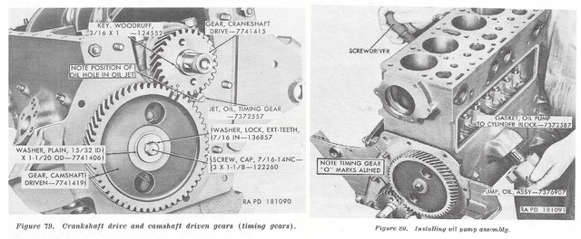
101. Install Oil Pump Assembly
a. When installing the oil pump assembly the following facts should be borne in mind.
(1) The oil pump is driven from the camshaft by means of a worm (spiral) gear. The distributor, in turn, is driven by
the oil pump by means of a tang on the end of the distributor shaft which engages a slot in the end of the oil pump shaft.
(2) Because the tang and the slot are both machined off center, the two shafts can be meshed in only one position.
(3) Since t,he position of the distributor shaft determines the “timing” of the engine, and since the position of the distrib-
utor shaft is determined by the position of the oil pump shaft, the position of the oil pump shaft wit,h respect to the cam-
shaft is critical.
b. Turn the crankshaft as necessary to bring the timing marks “0” on the crankshaft drive and camshaft -driven gears together (fig. 79).
c. Coat both sides of the oil pump to cylinder block gasket with liquid type gasket cement and install the gasket on the pump. Start the oil pump drive shaft into the opening in the left side of the cylinder block with the mounting holes in the body of the pump in alinement with the mounting holes in the cylinder block.
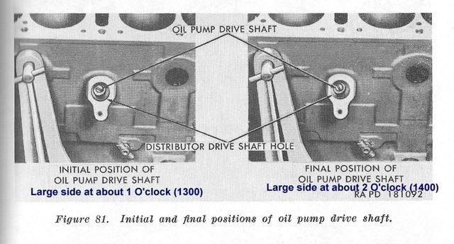
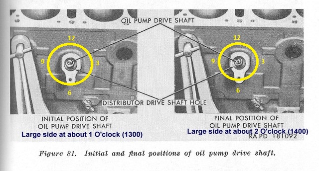
d. Insert a long blade screwdriver (fig. 80) into the distributor shaft opening on the opposite side of the block and engage the end of the oil pump shaft. Turn the shaft so that the slot is positioned at what would be the rough equivalent of the nine thirty position on a clock face (fig. 81), with the wider edge of the slot on top (nearer the top of the cylinder block).
e. Remove the screwdriver and, looking down the distributor shaft hole, observe the position of the slot in the end of the oil pump shaft to make certain it is properly positioned. Replace the screwdriver and, while turning the screwdriver clockwise to guide the oil pump drive shaft gear into engagement with the camshaft spiral gear, press against the oil pump to force it into its final position.
f. Remove the screwdriver and again observe the position of the slot. If the installation was properly made, the slot will be in the position roughly equivalent to the eleven o’clock position on a clock face (fig. 81) with the wider edge of the slot still on the top side. If the slot is improperly positioned, remove the oil pump assembly and repeat operations d and e above.
g. Coat the threads of the cap screws with plastic type gasket cement and secure the oil pump in place with two s/,e-18NG3 x 21/lock washer cap screws (fig. 18) installed through the body of the oil pump and into the cylinder block, and one 5/,,-18NC-3 x 1 lock washer cap screw (fig. 18) installed through the oil pump mounting
flange and into the cylinder block.
j. Install the distributor; before installing the distributor, however, check the position of the groove in the end of the oil pump drive shaft. If the groove in the end of the oil pump drive shaft is not in the “final” position shown in figure 81, turn the crankshaft as necessary to cause the oil pump shaft to move to the correct position. (1) To install the distributor, remove the distributor cover screws and remove the cover from the distributor. Install the distributor in the engine, guiding the distributor drive shaft into the drive shaft hole in the cylinder block. If the tang on the end of the distributor drive shaft does not
engage the groove in the end of the oil pump drive shaft, hold the body of the distributor and turn the distributor
rotor until engagement of the shafts is completed. (2) Install the 1/-20NC-2 x 5/8 cap screw (VU, fig. 12) and the
1/4-inch plain washer (NN, fig. 12) to secure the distributor in place.
(3) When the distributor has been secured in place, the distributor rotor should be in the position as shown in figure 106
(No. 1 cylinder firing position).
Note. If the rotor is in any other position, the oil pump shaft is improperly positioned. Refer to paragraph 101 for method of correctly positioning oil pump shaft.
(4) Connect the distributor to withshield wiper tee vent line (M, fig. 111) to the distributor and install the distributor
cover.
Wes K
45 MB, 51 M38, 54 M37, 66 M101A1, 60 CJ5, 76 DJ5D, 47Bantam T3-C & 5? M100
Mjeeps photo album: http://www.willysmjeeps.com/v2/modules. ... _album.php
45 MB, 51 M38, 54 M37, 66 M101A1, 60 CJ5, 76 DJ5D, 47Bantam T3-C & 5? M100
Mjeeps photo album: http://www.willysmjeeps.com/v2/modules. ... _album.php
-
jaybrabble
- Member
- Posts: 19
- Joined: Fri Feb 24, 2017 6:00 pm
-
jaybrabble
- Member
- Posts: 19
- Joined: Fri Feb 24, 2017 6:00 pm
-
wesk
- Site Administrator
- Posts: 16462
- Joined: Sun Apr 03, 2005 6:00 pm
- Location: Wisconsin
- Contact:
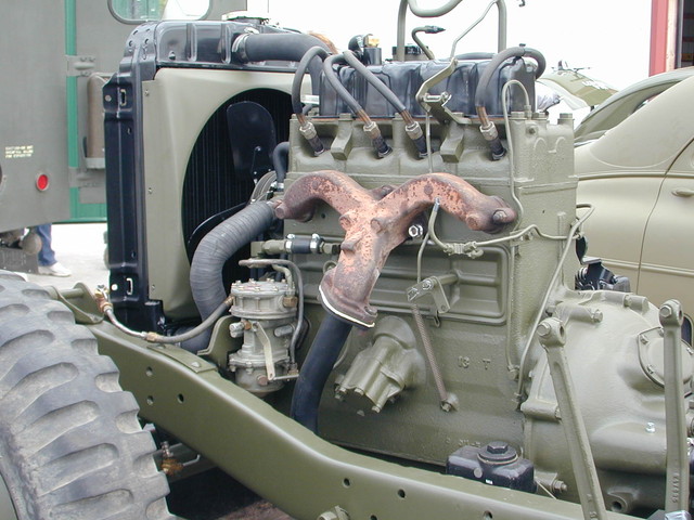
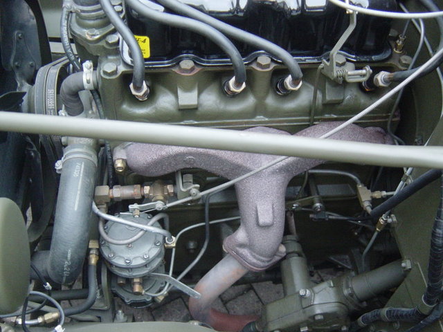
From these two photos you can see that both the exhaust pipe and the steering box may impede the removal of the oil pump to some degree. Plan on loosening or removing one or both.
Wes K
45 MB, 51 M38, 54 M37, 66 M101A1, 60 CJ5, 76 DJ5D, 47Bantam T3-C & 5? M100
Mjeeps photo album: http://www.willysmjeeps.com/v2/modules. ... _album.php
45 MB, 51 M38, 54 M37, 66 M101A1, 60 CJ5, 76 DJ5D, 47Bantam T3-C & 5? M100
Mjeeps photo album: http://www.willysmjeeps.com/v2/modules. ... _album.php
-
jaybrabble
- Member
- Posts: 19
- Joined: Fri Feb 24, 2017 6:00 pm
Thanks for that.
Another question. Or two
In figure 81 above, the picture on the left (initial position), below it states about 1 o'clock. It looks to me more like 10 o'clock
The picture on the right (final position) below it states about 2 o'clock. it looks to me like 11 o'clock.
Could someone please clarify?
Thanks
-
wesk
- Site Administrator
- Posts: 16462
- Joined: Sun Apr 03, 2005 6:00 pm
- Location: Wisconsin
- Contact:
Clock is the view forward. We are discussing the large side of the oil pump tang not the small side!
Wes K
45 MB, 51 M38, 54 M37, 66 M101A1, 60 CJ5, 76 DJ5D, 47Bantam T3-C & 5? M100
Mjeeps photo album: http://www.willysmjeeps.com/v2/modules. ... _album.php
45 MB, 51 M38, 54 M37, 66 M101A1, 60 CJ5, 76 DJ5D, 47Bantam T3-C & 5? M100
Mjeeps photo album: http://www.willysmjeeps.com/v2/modules. ... _album.php
-
skyjeep50
- Jeep Enthusiast
- Posts: 606
- Joined: Mon Feb 19, 2007 6:00 pm
- Location: Illinois
You can remove and replace the pump with the engine in - I have done it on my M38A1 without removing the exhaust pipe or steering gear. But it is a difficult almost one handed procedure. Removing and replacing the bolts is straightforward. You will probably have to scrape the remains of the old gasket off the engine and pump - have a new one ready to go. One challenge is the gearing is spiral in the block and in mating the pump gears, insertion tends to turn the pump shaft slightly. Which, if you are trying to attain a specific position for the distributor shaft, becomes a hit or miss challenge. I would start with the engine at TDC, distributor shaft where you want it to be, then wiggle the pump shaft into place. You may also want to prime the pump with some engine oil before insertion or prime the engine oil system before running to make sure the oil pump is pumping oil at the next startup. Of course, pre-oiling the pump makes the job of reinserting it pump an oily mess but that is half the fun!
1951 M38
-
wesk
- Site Administrator
- Posts: 16462
- Joined: Sun Apr 03, 2005 6:00 pm
- Location: Wisconsin
- Contact:
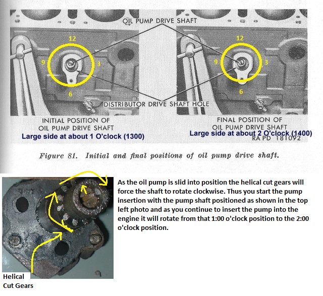
Perhaps this photo will make it simpler:
Wes K
45 MB, 51 M38, 54 M37, 66 M101A1, 60 CJ5, 76 DJ5D, 47Bantam T3-C & 5? M100
Mjeeps photo album: http://www.willysmjeeps.com/v2/modules. ... _album.php
45 MB, 51 M38, 54 M37, 66 M101A1, 60 CJ5, 76 DJ5D, 47Bantam T3-C & 5? M100
Mjeeps photo album: http://www.willysmjeeps.com/v2/modules. ... _album.php
-
jaybrabble
- Member
- Posts: 19
- Joined: Fri Feb 24, 2017 6:00 pm
-
jaybrabble
- Member
- Posts: 19
- Joined: Fri Feb 24, 2017 6:00 pm