Page 2 of 2
Posted: Sat Dec 20, 2014 9:26 pm
by Bretto
RICKG wrote:oilleaker1 wrote: I'm surprised you didn't get some galvenised tin and bend up a diffuser just like the original. Flappers and all! John
I'm sure Bretto could pull it off but it's WAY beyond my metal working skills.

Too much confidence in my abilities but thanks.
I would also think you could find a simple switch and wire it so you could switch it between 12/24 volts. That would give you 2 speeds.
Posted: Tue Feb 10, 2015 12:47 pm
by RICKG
I thought to follow up here with 2spd fan info:
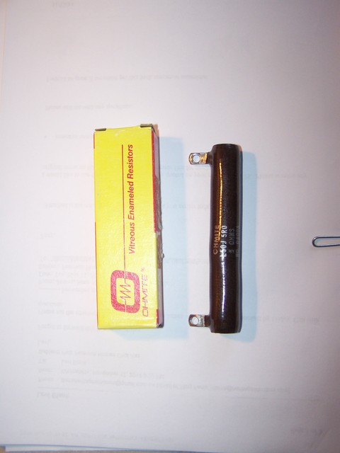
here is the 8710856 50W 5 ohm resistor, it measures 4" long, aprox 11/16 dia. I bought (2) for about 17 bucks shipped. Here's the link, Thx Brian!!
http://m.ebay.com/itm/391024488468?nav=SEARCH
I mounted it behind the Dash Data Plate for easy access. Below it is the 24V flasher for my signal stat 900.
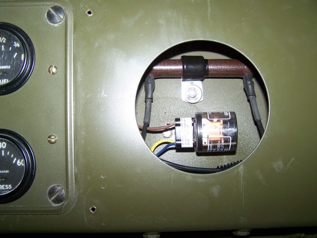
I insulated the connections with shrink tube to avoid shorts. I drove it last nite with the data plate off to get an idea of the heat generation-it gets too hot to touch but not hot enough to melt rubber. The low spd feature on the fan is welcome as the HI setting is just too much.
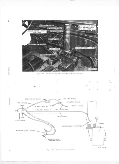
The wiring is per the schematic below:
Posted: Tue Feb 10, 2015 10:52 pm
by Bretto
Nice.
Curious, what's the voltage drop across that resistor when power is piped thru it? I'm still thinking you could of just wired in a switch in the middle of the batteries to toggle 12V or 24V to the motor and control the speed that way and not use any power to heat up a resistor. I don't know how much slower it would run at 12 compared to 24 though. Did you happen to check?
At least it's not blowing your face off now.
Posted: Tue Feb 10, 2015 11:06 pm
by Bretto
So let's say you got 2 or more loads in series in a circuit, they will all pull a certain number of volts but their sum will be the source voltage.
So if you say when the motor and resistor are live, source voltage is 24, the motor will measure some volt reading across its leads and likewise, the resistor will have a value across it's terminals, but their sum will be 24v in your case. If the voltage is 12V or there abouts across both loads, then you could of got by what I said on the last post. If the voltage is substantialy higher than 12 on the resistor then it's really pulling power. If so though then again you could of done the 24/12 split and used a lighter resistor on the 12V circuit.
Sorry for rambling........off to bed now.
Posted: Wed Feb 11, 2015 12:18 am
by wesk
It is never a good idea to split the matched pair of 12 V military batteries up to service both 12 and 24 V equipment. One reason is the unequal loads applied to the batteries force early aging of the higher loaded battery. The other is safety cause sooner or later someone is gonna screw up and apply a 24 volt load to the 12 volt circuit which will result in overheating of the 24 volt component or worse yet apply 24 volt to a 12 volt component usually burning that 12 volt unit up. Even when we want to run 12 volt equipment off the 24 volt battery on aircraft we use a regulated power supply or a resistor. Mix & match almost always results in confusion!