Page 3 of 3
Posted: Thu Dec 22, 2016 8:29 pm
by wesk
I think the answer is already here. The M38 and M38A1 series used the same 4 wire switch throughout production so the requirement to secure it existed all along. The bracket Brian pointed out will work so long as the connector used between the pin in wire #85 and the bracket contains no conductor.

Posted: Thu Dec 22, 2016 9:31 pm
by keats
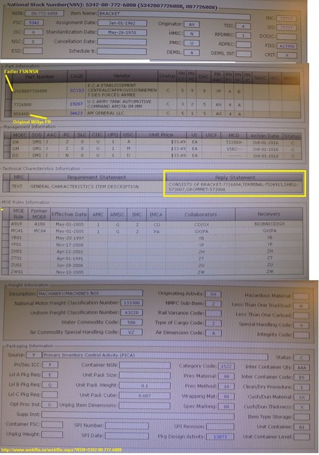
Not that I doubted you but felt your resolution needed more proof of the "dummy connector". Well, I did some more digging and found on page 157 of the ORD 9 for the M38A1 the part # 7524913 - terminal non-conductor (circuit closure cap). That must be the part you figured had to be there, and it does have its own part #!!
Unfortunately, this part # is not listed or mentioned in the M38 ORD 9.
Its great when a good question is resolved.
Posted: Fri Dec 23, 2016 12:06 am
by wesk
Unfortunately, this part # is not listed or mentioned in the M38 ORD 9.
As I mentioned in reply to Brian above the 7726804 bracket he mentions was part of the assembly 7726808 (Bracket Assy) in the M38A1 ORD 9. The M38 ORD 9 neglects to list the parts of the assembly 7726808. But the M38A1 ORD 9 does list both the entire assy and the component parts.
I am sure that 7524913, Terminal non-conductor was part of the assy 7726808 on both the M38 & the M38A1.
Posted: Fri Dec 23, 2016 10:31 am
by wesk
Another piece of the puzzle is the stand down and force reductions / budget cuts after the Korean war. An example of this was the late 1953 dropping of the fording system to reduce M38A1 acquisition costs. This is also why many parts previously shown in ORD 9's as an assembly with no breakdown of individual parts suddenly began appearing with assembly parts breakdowns that reduced spending by buying a lesser part. The military supply system was equipped in the late 50's and on to flag assembly numbers and automatically query the requester if individual parts would suffice.
Posted: Fri Dec 23, 2016 8:00 pm
by 4x4M38
Terminal non-conductor.
Ya gotta love the military for descriptions.
My father in law had no middle name.
Officially he had to have one or have the anomaly described.
His "middle name/description" was NMI, i.e., no middle initial.

Posted: Wed Aug 30, 2017 8:42 pm
by RonD2
Not trying to resurrect the dead here, just an answer to the original question, which unless I missed it seems to be "TBD"?. Where exactly (what hole) does it mount?
I got one of these G244-7726808 brackets included in a NOS kit that included the following tagged information:
"FSN 2920-796-2655, Parts Kit, Contract DAAE07-73-C-4320, This kit for use with switch Ord Part Number 8380699 (FSN 5930-699-9438) to replace switch Ord Part Number 7760409 (FSN 5930-776-0409)."
The military wire number list I have says "85" is "Low Air Pressure Indicator Light". Pretty sure I don't have one of those on my M38 (even if it is converted to 12 volts).
It turns out I'm going to use that wire on the ignition switch for a circuit so I don't need the closure bracket, but would like to mount it where it belongs anyway --- for the next guy, or maybe an extra point or three in the judging contest.....
I figure if I don't screw it down now somewhere close to where it belongs I'll lose the darn thing....

I can take a photograph or two of it if it helps?
Posted: Thu Aug 31, 2017 8:01 am
by 4x4M38
Hi Ron,
So far one wiring protector with a hole, several without, and one
bracket like yours mounted to the right hand steering column bolt.
Maybe we need to go on a manual picture hunt and see if we can find
that bracket hiding in the background somewhere.
I'm planning on using 85 for my solenoid power on my 12 volt
converted vehicle. I'll run it through a 12 volt foot switch.
14 gauge should be sufficient all the way to the solenoid.
Posted: Thu Aug 31, 2017 9:19 am
by RonD2
Hey Brian, last night I was looking through the ORD9 for the 2 screws (10-24's) that hold the bottom edge of the gauge splash panel to the bottom edge of the dash through the 2 weld nuts on it. Couldn't find them (they don't appear to be listed with the splash panel).
I'm thinking I might find 2 different length screws, and the longer one (with a nut on top of it) could hold the G244-7726808 "circuit closure bracket" in place and within reach on the left-facing screw. Still looking....
Posted: Thu Aug 31, 2017 8:14 pm
by keats
I think the 4 screws are listed in the Ord 9 right under the listing for the strap support for the gauge guard on page 154. Listed as all the same size
Posted: Thu Aug 31, 2017 8:52 pm
by RonD2
Hi Gary. Thanks! I'd might've discovered that myself.....eventually. Don't be spoiling the rookies now.
It still has to mount somewhere. What's that STUD, Mounting, Instrument Panel Wiring Harness, G741-7526594 that follows right after those screws on page 154?
I guess only a photograph will tell........not me guessing.

Posted: Thu Aug 31, 2017 10:56 pm
by keats
That stud is probably the stud the spider harness attaches to on the speedometer.
This has been a mystery for awhile now. I don't think it was mounted on the steering column bracket as the hole in the wire connector is to small. The hole in the gauge shield may have been utilized, but several members and my own observations of M38's show no hole. Perhaps the hole was deleted after a point in time, but why?
Perhaps someday an answer will be found.