Page 1 of 1
gauge installation
Posted: Mon Jan 04, 2016 3:29 pm
by 4x4M38
I have a temperature gauge for my 12 volt M38.
Can anyone tell me how to wire it?
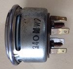
Stewart Warner 431800
340M W7
Thanks!
Brian
gauge installation
Posted: Tue Jan 05, 2016 8:34 am
by idiocrates
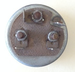
I'm only guessing mind you, but I think the two studs that are side by side in line are for attaching the "U" shaped bracket that holds the gauge in the instrument panel. That would make the single post just above these two the lug where you'd attach the wire from your electrical sender. And if I'm seeing it correctly, it looks like a push-on lug just to the right and below this post where you'd probably put a good solid ground on the body of the gauge.
Do you know, is this gauge illuminated or indicate anything else other then just water temperature?
Gauge installation
Posted: Tue Jan 05, 2016 9:18 am
by idiocrates
I hate it when I have to argue with myself but I think I gave you some really bum advice above. The three lugs or posts.......are there any letters stamped or printed next to them? One should be ground and be labeled "G", one should be labeled "S" and be the wire from the sender and one should be labeled "I" and be battery coming to the gauge from the ignition switch or battery source. The ground lug should be fairly easy to locate using an ohm meter between the body of the gauge and the three lugs. Two should indicate infinite resistance (no continuity) and one should indicate very close to zero ohms (continuity). Then I should think the other two don't really matter. One post will go to the ignition source and the other to the sender. If you hook them up backwards the gauge will indicate backwards and if so simply swap the two connections around.
That being said, if all three posts are utilized this way I'm not real sure how the meter would be held in place in the panel.
Posted: Tue Jan 05, 2016 11:08 am
by wesk
Brian,
It helps to show us the face of the gauge and the gauge's mount bracket. I hope you have the mated sender with this gauge. If not matching a correct resistance sender will probably cost more then just buying a less troublesome brand new mechanical temp gauge which will never give you any electrical issues.
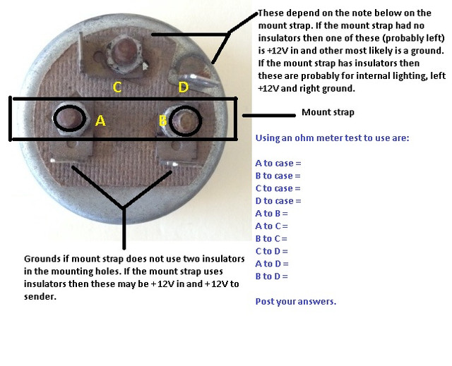
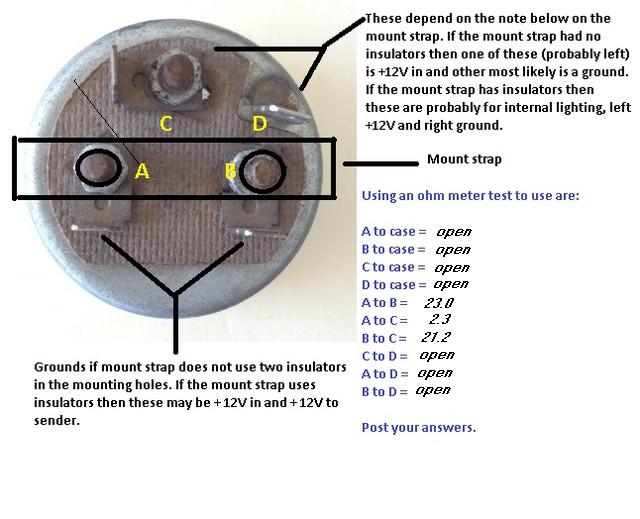
Do the tests shown below and post the results.
Posted: Tue Jan 05, 2016 1:10 pm
by 4x4M38
Thanks for the replies, and the test especially Wes.
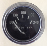
I had thought of pulling the bezel, and will anyway as the windows are light blue plastic which need to be changed to clear.
As you can see, three of the posts are insulated, and the one is soldered to the case. The gauge did not come with a bracket. I have contacted Summit,. who recommended the 280EA sender for this gauge, though they did not have instructions for installation.
I'll test the gauge per your instructions Wes, and report back.
It is handy to find gauges like these with light windows, so you can use the original lighting. I found a mechanical oil pressure gauge with windows as well, but have not been able to find a mechanical temp gauge so built.
Posted: Tue Jan 05, 2016 1:47 pm
by 4x4M38
Resistance results:
Posted: Tue Jan 05, 2016 11:25 pm
by wesk
I would suspect this gauge will have issues.
It would appear that A, B & C are all used for power in or out which is why they are insulated from the case.
Some gauges require a power in for the needle and a power out to the sender to complete a circuit to ground. I would suspect A & B to be those two.
Some gauges have the third +12VDC terminal for internal lighting which yours does not have. Those remaining gauges with a third power terminal use it to operate a stabilizing or sample current from +12 VDC in through the case at D to a separate case ground.
The open indication is very odd for D. Since it is clearly soldered to the case you should have had 0 resistance between the D terminal and the case.
It would be interesting to hear your Summit salesperson explain how they determined which modern sender would work best for that very old gauge .
Also you are in a pickle now to find an insulated mounting bracket to fit that gauge.
I would not waste so much of my valuable project time on altering and risking a failure if it is not already failed but would continue my search for a new unit that is mechanical type. KISS Keep It Simple St_______. is the addage that comes to mind.
You already have wire # 27 for a power feed so just get a nice mechanical temp gauge with a electric lamp and use the same color bulb you are using in the two GI dash illumination lamps and no one will ever know the difference.
Posted: Wed Jan 06, 2016 8:55 am
by 4x4M38
Hello Wes,
Thanks for the info.
I made a mistake in reporting. D is indeed zero resistance to
the case.
I don't know how Summit determined the sender as they were
unable to even tell me the gauge voltage.
I was wondering if maybe the third terminal was for 6 volts.
Of course your suggestion is right. I have already purchased
a five wire spider for use with my voltmeter. Simple enough
to use one lead for gauge lighting. I could however add a third
wire to the light cable as mine is nonexistent. Plenty of Douglas
connectors in the parts box along with spare wire.
As I noted earlier I was able to find a 0-120 mechanical
pressure gauge with the light windows.
Thanks again for the help and discussion.