Page 1 of 1
M38 fuel tank bolts for the sending unit/filter assembly
Posted: Mon Jan 11, 2016 9:05 pm
by pickle
Hello all,
trying to find out what are the bolt sizes and head type for mounting the sending unit and filter assembly on the fuel tank? was it a screw head or standard hex bolt head? tried to look in ordinance manual but could not find it...My old tank was modified and it had Robertson head screws.
thanks guys.
mK
Posted: Mon Jan 11, 2016 11:44 pm
by wesk
In the SEP 55 M38 ORD 9
for the filter page 83 7 lines up from bottom of the page:
Screw, , MACH, rd-hd, S, cd or zn -fin, No 8-32NC-2x7/16. 12 Ea.
" Machine-round-head-cad or zinc finished-size 8-32-fit class 2 -length 7/16"
for the fuel sending unit page 163 first line below Unit, sending fuel gauge:
Screw, , MACH, rd-hd, S, cd or zn -fin, No 8(0.164)-32NC-2x7/16 5 Ea.
" Machine-round-head-cad or zinc finished-size 8-32-fit class 2 -length 7/16"
Superseded by by SCREW 120583
Screw, , MACH, rd-hd, S, cd or zn -fin, No 8(0.164)-32NC-2x7/16 5 Ea.
" Machine-round-head-cad or zinc finished-size 8-32-fit class 2 -length 1/2"
Supersedes SCREW 133043
These are slotted type flat tip screw driver heads. The translation of the abbreviations I used above can be found in the Same ORD 9 pages 5 & 6.
This ORD 9 is a free PDF download on our downloads page.
Here's is what they look like.
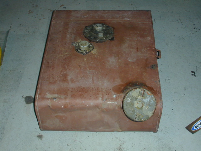
For more detail view the larger file size of this photo:
http://willysmjeeps.com/v2/modules/gall ... CN0007.jpg
Posted: Tue Jan 12, 2016 6:09 am
by oilleaker1
Before you jump, note that the reproduction sending units are thicker than original and the 8-32 screws will be too short. They also have tall protruding brass rivit rings holding the sections of the sender together and you will need a thick gasket or those rings hold it off the surface and it leaks fuel. Ask me how I know this! I also permatexed the screws when installing or they will leak. John
Posted: Tue Jan 12, 2016 8:10 am
by 4x4M38
Hi John,
Good points.
The screws should not leak as the ring should be
soldered to both the raised lip of the tank as well
as the outer edge of the ring.
However, I have not seen much in the way of solder
around the lip. This will allow gas to slosh out and into
that well area. Permatex is a good idea.
Be aware, that if repairs have been done to the tank/ring,
that well area below the ring may have solder in it, and
the ring may not be sitting flush with the lip of the tank.
Both will impair screwing the 7/16" jobbies in.
Ask ME how I know.
Headed to a shop this week to get my ring adjusted after
it was repaired and installed at a tilt. No way will it seal.
Take care,
Posted: Tue Jan 12, 2016 9:01 am
by wesk
Since you only asked about the screw head shape I only posted the screw descriptions. If you look carefully at the list of attaching parts which appears just below the filter entry you will also see where originally soft finishing washers were used with the 12 screws. But these were later superseded with lead washers.
The technical writers for both the manufacturers and the Army seldom were mechanics and never had to use their own product in the field. This is why when researching parts in these old supply manuals it pays to read slowly and all the way to the end of the subsection. As with the filter above why a technical writer would list the screws and lockwashers under the filter assembly entry then skip several lines to below the filter's attaching parts and list the sealing washers is beyond any common sense rules.
fuel tank hardware
Posted: Tue Jan 12, 2016 9:42 pm
by pickle
Thank you guys very much. I have the 55 manual, but i was trying to find on page 63 looking for it on the diagram!
so if I understand the supersceded part, I should still be good with 7/16 for filter assembly and 1/2 for sender unit because I have an M38 original tank and original fuel filter assembly and sender unit (not sure if either work right now.)
Is there a way to test units with voltmeter on bench?
question of the filter element....what is best - original or I have seen a screen version.
Posted: Tue Jan 12, 2016 9:49 pm
by wesk
The gauges and senders have a test regimen in the TB 9-2300-228-20 Tactical Transport and Combat Vehicles: Troubleshooting for Instrument Cluster Gages, Switches, Circuit Breakers, Sending Units and Related
Wiring dated 8 July 1960. which you can also download free on our downloads page:
http://www.willysmjeeps.com/v2/modules. ... tit&lid=46
I prefer the stock filter but fabricating a mounting system to the original housing for a modern filter element is the way to go.
If you are all stock the 7/16" length screws will work fine. The supersedure to the 1/2" length was precautionary I believe to ensure complete thread engagement.
Length of filter assembly and state of filter
Posted: Sun Feb 14, 2016 10:37 am
by pickle
thanks for all the help Wes.
One thing I noticed is when I took out my filter assembly, one mechanic cut the bottom portion of it off, so that the clamp portion was completely missing. The filter had been in place for long time, is there any other concerns of not having the clamping portion at the bottom of filter other than extra securement? the filter line does go to bottom of filter.
(see attached photo)
secondly, I took the filter and it noticed it was like old leather. An friend recommended carb cleaner, so i soaked it, and it did clean it. I did notice movement through the filter with fluid and air. Is the filter still good?
http://willysmjeeps.com/v2/modules.php? ... _photo.php
Posted: Sun Feb 14, 2016 10:59 am
by wesk
Vibration from a lot of offroad use would dictate having the extra support.
I would start out with a new element. It's not worth the Pita to take it apart again a month or two later because you tried to save a buck.