Oil Pump and Distributor Installation
TM 9-1804A M38 Engine & Clutch
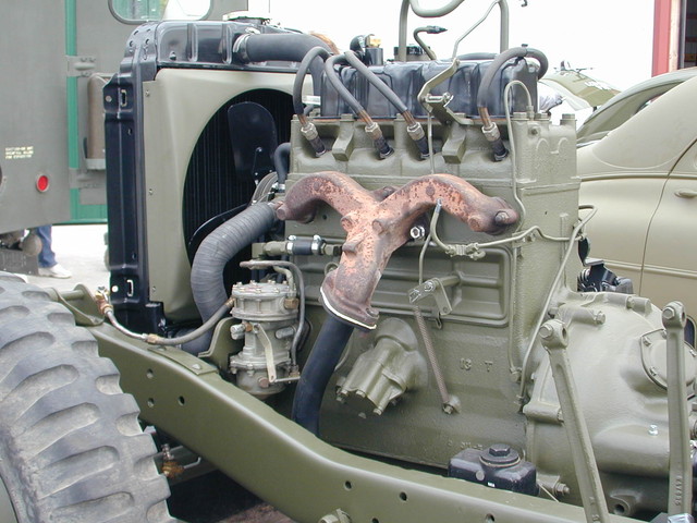
92. Install Oil Pump
Place a finger on No. 1 spark plug hole, and turn the crankshaft until No. 1 piston is coming up on compression stroke. Continue turning the crankshaft until the timing mark “5’” on the flywheel is alined with the index mark in the center of the timing hole on the engine rear plate (fig. 76). Install the distributor in the cylinder block (par. 98)) temporarily. Set the rotor on No. 1 firing position with the ignition points just breaking. Immerse the oil pump in a container of oil (same grade as used in the engine), and turn the inner rotor and shaft until the oil flows from the outlet hole in the oil pump housing. Place a gasket on the oil pump and, with the wide side of the slotted end of the shaft assembly up, install the oil pump on the engine, making sure the slot in the oil-pump shaft engages with the distributor shaft while the rotor is on No. 1 firing position with
ignition points just breaking. Install the three yrs-inch cap screws that secure the oil pump to block. Remove distributor.
98. Install Distributor (fig. 33)
Place a thumb over No. 1 spark plug hole, and turn the crankshaft until No. 1 piston is coming up on compression stroke, and the timing mark “5”” on the flywheel is alined with the index line on the engine rear plate. Install the distributor on the engine, and rotate the rotor until the distributor shaft engages with the oil pump shaft. Install the cap screw in the distributor hold-down clamp, and turn the distributor until the points are just breaking. Tighten the bolt in the distributor hold-down clamp.
TM 9-8015-1 M38A1 Engine & Clutch
101. Install Oil Pump Assembly
a. When installing the oil pump assembly the following facts should be borne in mind.
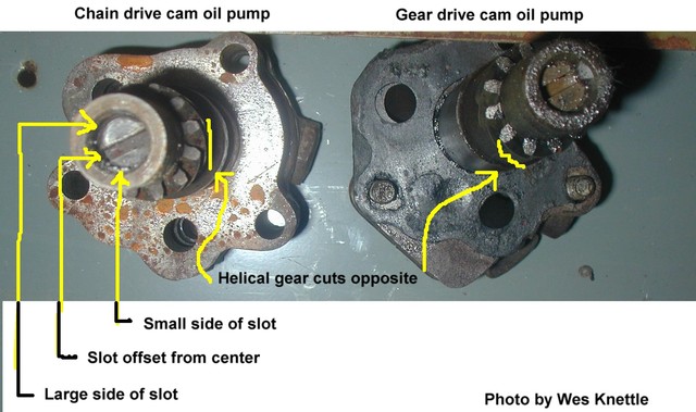
(1) The oil pump is driven from the camshaft by means of a worm (spiral) gear. The distributor, in turn, is driven by
the oil pump by means of a tang on the end of the distributor shaft which engages a slot in the end of the oil pump shaft.
(2) Because the tang and the slot are both machined off center, the two shafts can be meshed in only one position.
(3) Since t,he position of the distributor shaft determines the “timing” of the engine, and since the position of the distrib-
utor shaft is determined by the position of the oil pump shaft, the position of the oil pump shaft wit,h respect to the cam-
shaft is critical.
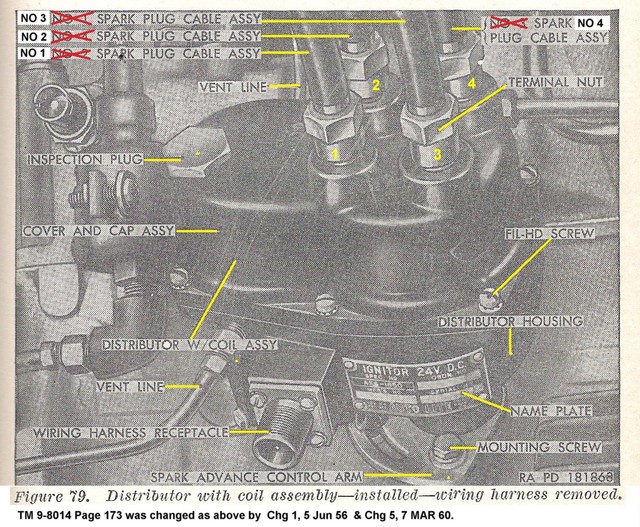
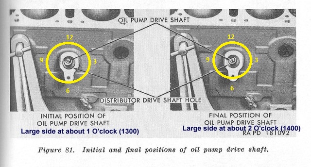
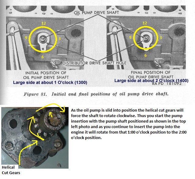
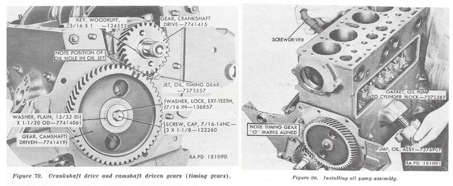
b. Turn the crankshaft as necessary to bring the timing marks “0” on the crankshaft drive and camshaft -driven gears together (fig. 79).
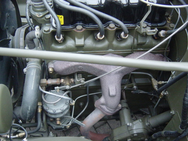
c. Coat both sides of the oil pump to cylinder block gasket with liquid type gasket cement and install the gasket on the pump. Start the oil pump drive shaft into the opening in the left side of the cylinder block with the mounting holes in the body of the pump in alinement with the mounting holes in the cylinder block.
d. Insert a long blade screwdriver (fig. 80) into the distributor shaft opening on the opposite side of the block and engage the end of the oil pump shaft. Turn the shaft so that the slot is positioned at what would be the rough equivalent of the nine thirty position on a clock face (fig. 81), with the wider edge of the slot on top (nearer the top of the cylinder block).
e. Remove the screwdriver and, looking down the distributor shaft hole, observe the position of the slot in the end of the oil pump shaft to make certain it is properly positioned. Replace the screwdriver and, while turning the screwdriver clockwise to guide the oil pump drive shaft gear into engagement with the camshaft spiral gear, press against the oil pump to force it into its final position.
f. Remove the screwdriver and again observe the position of the slot. If the installation was properly made, the slot will be in the position roughly equivalent to the eleven o’clock position on a clock face (fig. 81) with the wider edge of the slot still on the top side. If the slot is improperly positioned, remove the oil pump assembly and repeat operations d and e above.
g. Coat the threads of the cap screws with plastic type gasket cement and secure the oil pump in place with two s/,e-18NG3 x 21/lock washer cap screws (fig. 18) installed through the body of the oil pump and into the cylinder block, and one 5/,,-18NC-3 x 1 lock washer cap screw (fig. 18) installed through the oil pump mounting
flange and into the cylinder block.
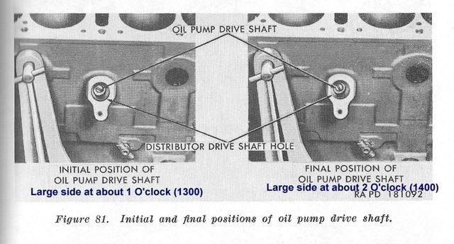
j. Install the distributor; before installing the distributor, however, check the position of the groove in the end of the oil pump drive shaft. If the groove in the end of the oil pump drive shaft is not in the “final” position shown in figure 81, turn the crankshaft as necessary to cause the oil pump shaft to move to the correct position. (1) To install the distributor, remove the distributor cover screws and remove the cover from the distributor. Install the distributor in the engine, guiding the distributor drive shaft into the drive shaft hole in the cylinder block. If the tang on the end of the distributor drive shaft does not
engage the groove in the end of the oil pump drive shaft, hold the body of the distributor and turn the distributor
rotor until engagement of the shafts is completed. (2) Install the 1/-20NC-2 x 5/8 cap screw (VU, fig. 12) and the
1/4-inch plain washer (NN, fig. 12) to secure the distributor in place.
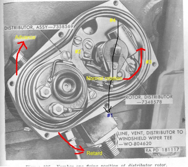
(3) When the distributor has been secured in place, the distributor rotor should be in the position as shown in figure 106
(No. 1 cylinder firing position).
Note. If the rotor is in any other position, the oil pump shaft is improperly positioned. Refer to paragraph 101 for method of correctly positioning oil pump shaft.
(4) Connect the distributor to withshield wiper tee vent line (M, fig. 111) to the distributor and install the distributor
cover.