Page 1 of 1
hand drawn headlight wiring schematic
Posted: Thu May 10, 2018 11:48 am
by Trip
I saw this hand drawn wiring schematic for an M38 and and A-1 on here a while back The individual listed wire lengths and wire numbers for the headlight wires. Also listed number of male and female douglas connectors needed. Written on yellow legal paper. One page for an M38 and one page for an A-1
I cannot find this drawing again to save my life and I have been searching for 2 weeks.
I know someone (probably Wes) will reply and say it is right here! If you can point me to the location, I would appreciate it.
Charles
Posted: Thu May 10, 2018 5:25 pm
by Kendall
That was my hand writing. These can be found on my Photo Gallery page (Kendall) on the bottom of page 1 and the top of page 2.
Hope they help you out.
Kendall
Posted: Thu May 10, 2018 7:03 pm
by Trip
Thank you very much !
Posted: Fri May 11, 2018 5:05 am
by 4x4M38
Yessir!
Handy as a pocket on a shirt!
Thanks for taking the time Kendall.
Posted: Fri May 11, 2018 5:16 am
by 4x4M38
Here is the link to page 1:
http://www.willysmjeeps.com/v2/modules. ... _album.php
By the way, everyone can link their photo pages to their auto signature so
folks don’t have to go searching all over for them.
See my sig below, as well as Wes’.
Take care,
m38 wiring diagram
Posted: Sat May 12, 2018 1:09 pm
by gunnerb17
Sir Really like the M38 wiring diagram you drew. Could you please explain why the power lead #27 is on the opposite side of the temp gage as compared to the oil pressure and the fuel gage? Thanks
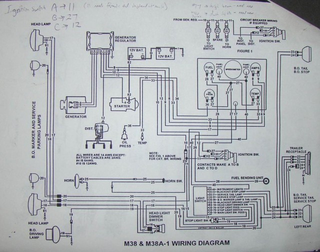
Kendall's wiring diagram
Posted: Sat May 12, 2018 4:55 pm
by 4x4M38
it looks like a typo and error in the drawing.
More to the point is the little black/white indicator representing the
connector is wrong. Black over white indicates power in.
In this case the two connectors are shown incorrectly.
Posted: Sat May 12, 2018 4:57 pm
by wesk
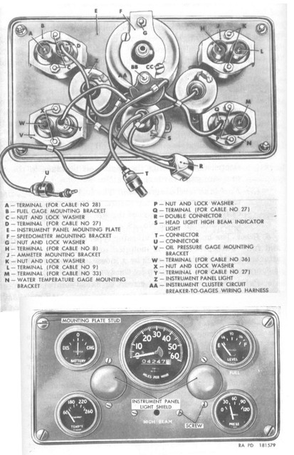
The most logical reason is since the #27 spider harness fastens in the middle they wanted to keep it's connections oriented towards the center of the cluster.
Posted: Sat May 12, 2018 7:10 pm
by 4x4M38
I agree, Wes except they still got the male vs
female connector symbol on the drawing
wrong.
Posted: Sat May 12, 2018 11:09 pm
by wesk
Who is they? The M38 manual TM 9-8012 shows them correctly in it's wiring diagrams which do not use the same scheme as kendall's.
However I did a wee bit more research and the M38 TM 9-804 shows all three gages with the male terminal on the right as viewed from the rear of the cluster. Then a quick check of the M38A1 TM 9-8014 showed the same thing.
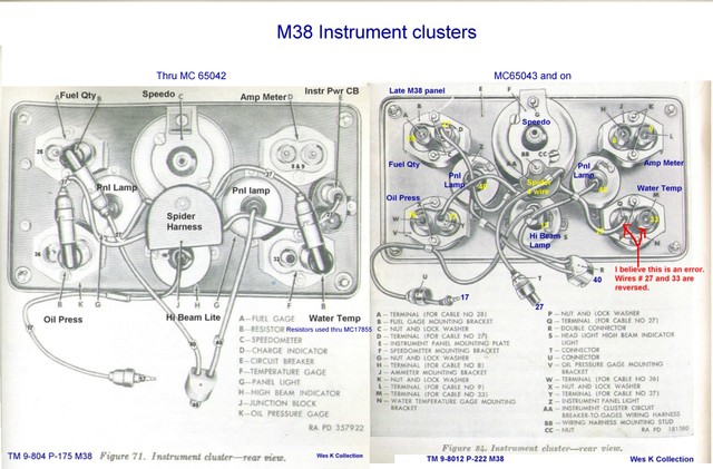
I had spotted this error several years ago as can be seen in this old illustration I loaded way back.
Posted: Sun May 13, 2018 6:38 am
by 4x4M38
Yes Kendall’s wiring diagram.
I bet he used that incorrect illustration before you corrected it.
In any case you guys are both awesome! You for catching and correcting
60+ year old incorrect illustrations and Kendall for making the wiring diagrams and wire length charts!