Page 1 of 1
Fuel line routing
Posted: Sun Mar 24, 2019 3:41 pm
by oldbluedodge
Ok I’ve exhausted my search for good photos or explanation of the routing from tank to pump. I don’t want to redo so I figure I will ask.
I read an old post that had a link to some pics of Wes’s. The link must be dead. If anyone can direct me that would be great.
Also I’ve read the flashing procedure for the gen polarity. Couple questions, what part of the starter do I brush my lead on? Also I’m assuming that the batteries should be disconnected.
Thanks again for all the help
Drew
Posted: Sun Mar 24, 2019 9:18 pm
by kenperkins
look in the photo gallery here...go to Wes' albums..fuel systems... and look at page 4
Posted: Sun Mar 24, 2019 10:45 pm
by oldbluedodge
Already have looked at more than just wes’s. He put up a link on a thread with the same topic. That link is not to this site. So, it has different pics. The link seems to be dead.
Posted: Sun Mar 24, 2019 11:45 pm
by wesk
Drew, You neglected to tell us which model jeep you want this info for. I suggest you go to your profile and list the model and year of your jeep in your signature element right after your name. Then everyone can more safely assume you are discussing that jeep model.
Also are you flashing the field on a standard 24 V 25 A military generator with the stock military wiring harness setup? Flashing the generator field is done with battery connected.
If stock 24V 25A DC military generator:
Disconnect the Gen-Reg Cable at the generator end, note where the alignment lug is (where the slot on the plug of the cable lines up) on the top of the elbow on the Generator. There are three terminals in there, you want the "B" terminal, it is the lower left when looking in to the elbow, and is actually marked. Take a Jumper from the "B" terminal on the generator and just only one time just quickly brush the hot terminal on the starter.
Hot terminal on your starter is the terminal that has the 24V battery power cable connected to it.
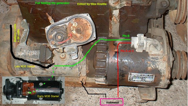
This illustration is for full fielding the 24V 25A generator to test it's maximum output. If you wish only to polarize the Generator then delete the volt meter and it's red & black wires.
Using a short piece of 16 Gauge wire set up like the green wire in the illustration you can clip it to Pin B on Generator and just for a moment brush it against the +24V terminal on whichever starter you have.
Posted: Wed Mar 27, 2019 8:47 pm
by oldbluedodge
Thanks again
I added my vehicle to my signature. I have a late model m38. My guess is 52.
I do have the tag from the body but that is it. I have just gone off of little things that I referenced back to Ryan great book.
This has been a long project and it’s so near to being back on the move.
I took some good advice I read on a recent post and read every TM I could find and the ORD. I think I have it routed right, bu would love a pic or two just to be sure.
The gen and starter pic was perfect
Thanks again.
Posted: Wed Mar 27, 2019 9:11 pm
by mdainsd
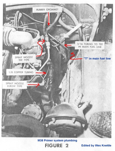
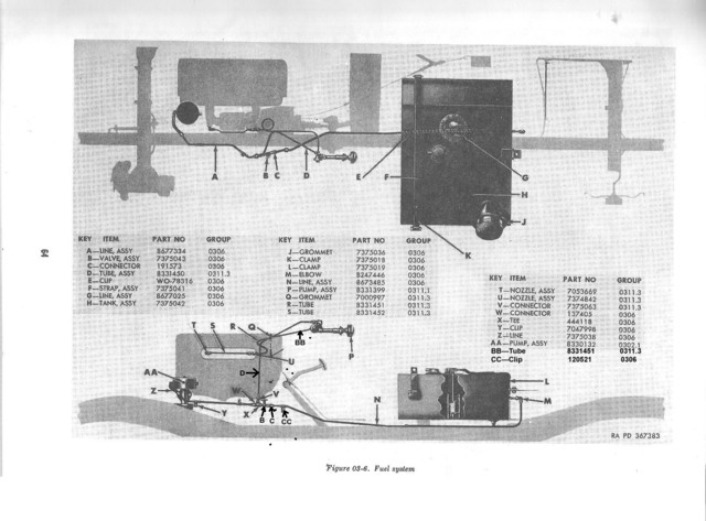
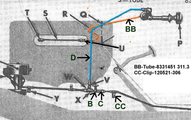
Ryan's book is about as close s you will come to a good illustrationof the fuel system routing. Page 60 at the top. That part of these Jeeps is almost impossible to photograph.
Starting with the right hand illustration.
The first thing coming out of the tank ("L" in Ryan's illustration)is a 1/4" piece of tubing, both ends being flared, it routes from the fuel tank pickup connection rearwards along the tank top to the rear edge. There it take a 90 degree bend to head straight down. Next bend is another 90 degree bend rearwards which sends this tube through the hole in the riser portion of the tub.
Use the free down load parts list on this site, it will tell you the length of this tube and all the rest.
Next comes a 90 degree reverse flare fitting ("M" in the illustration).
next comes "N" the longest tube in the fuel supply plumbing. It starts at the 90 degree fitting make a 90 degree turn which sends it forward along the inside of the frame rail. It makes a jog through the hole it the toe board gussets of the tub,
That takes us into the left hand illustration on page 60. The little part unidentified right below the junction of the pedal and the lever is a 1/4" "P" clip that secures the fuel line to the toe board gusset.
From there forward are fittings and a valve all identified in the SNL parts list avail able here.
Forward o that is one more piece of 1/4" reverse flared tubing and the flex hose that connects to the fuel pump inlet.
Hope this helps more than confuses...

Posted: Wed Mar 27, 2019 10:39 pm
by wesk
Posted: Tue Apr 02, 2019 12:37 am
by oldbluedodge
Thanks again
This is what I’ve needed. I got the fuel and most of the wiring done. Wouldn’t have gotten it correct without all of your help
Drew