Page 1 of 2
Fireworks under the hood! #12 wire
Posted: Thu Mar 11, 2021 6:20 pm
by JeepdaddyRC
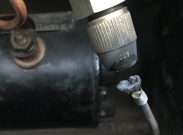
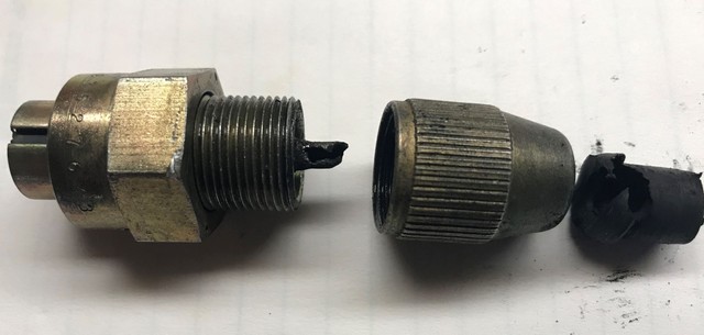
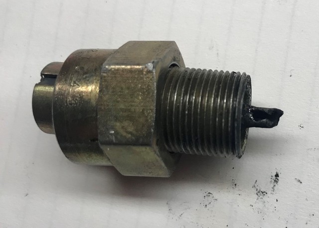
I was watching this M38A1 idle, when I heard a pop and saw sparks - the #12 wire separated from its connector at distributor. I did not bump it.
Glad it happened in the driveway - obviously the engine quit.
I bet I twisted it when removing the coupler to replace the radio suppression wire inside distributor.
What gauge wire and best way to reconnect/splice?
Posted: Thu Mar 11, 2021 8:05 pm
by JeepdaddyRC
I see that Kaiser Willys has the part.
http://willysmjeeps.com/v2/modules.php? ... ic&t=11563
But not correct for the M38A1. Will require splicing.
What is the best way to splice that into current #12 wire?
Posted: Thu Mar 11, 2021 8:07 pm
by RonD2
This is good fresh new military spec vehicle wire, but 50 feet might be too much if you want to wait for sparks to fly each time instead of inspecting all your wire carefully and replace it before that happens...
 https://www.ebay.com/itm/50-PRESTOLITE- ... SwQN5aa5od
Splicing new good wire to rotten bad wire is never a good idea. Replace the entire wire from start to end with brand new wire, properly assembled.
Do you own a soldering iron?
I'm having deja'vu about bad wire from your other posts. Don't say I never told you so.

Good luck!
Posted: Thu Mar 11, 2021 11:00 pm
by wesk
Posted: Fri Mar 12, 2021 9:07 am
by JeepdaddyRC
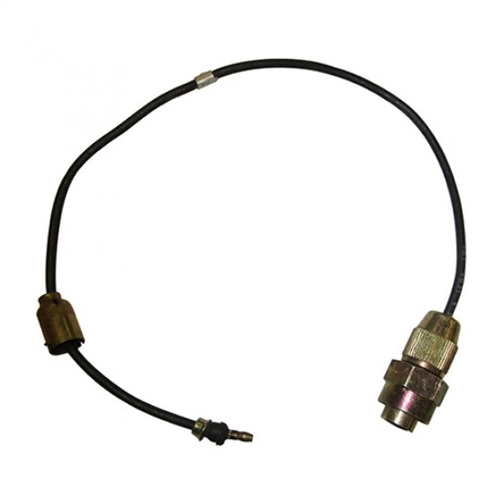
John at Midwest Military and Kaiser Willys have the NOS M series truck distributor connection. For the M37, it is a direct plug and play. However, the M38 and M38A1 require some type of solder/shrink tube splice to the 12 wire.
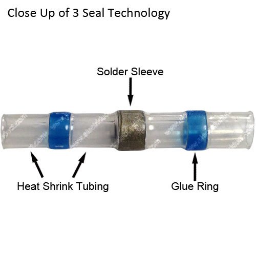
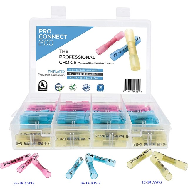
What is your feeling on these waterproof solder heat shrink connections for the splice into #12 wire?
Posted: Fri Mar 12, 2021 11:17 pm
by wesk
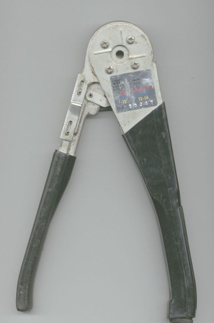
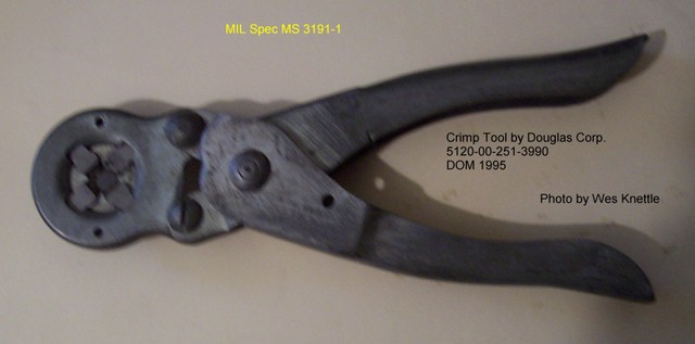
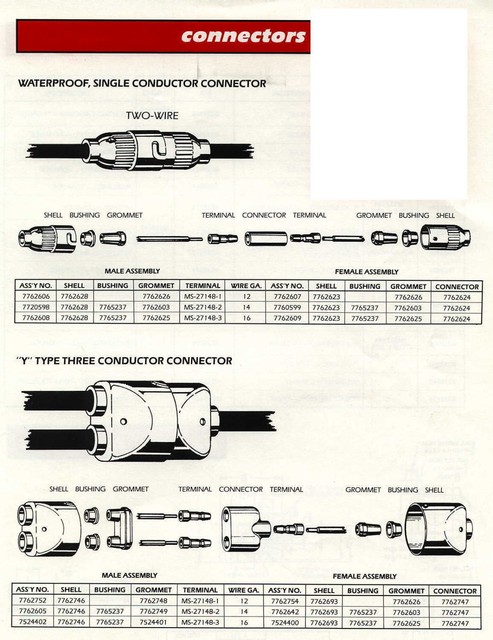
Why would you need a splice. The original installation is just like John's photo with the threaded connector on one end and the standard waterproof metal Douglas connector on the other end? If you do not wish to complete the run all the way to ignition switch just add a Douglas connector to the rest of #12 wire that is hanging from the firewall. All you need is a crimper and the opposite half of this single Douglas connector in the top half of this page that matches the gage of your wire:
As mentioned earlier good solid reliable electrical work must always follow the industry standard repair process. Slicing a new wire to an old wire that just failed due to age is not a good way to go.
Posted: Sat Mar 13, 2021 2:16 pm
by JeepdaddyRC
Why didn't I think of that?
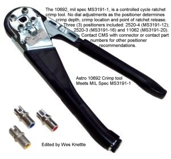
Ordered a BUCHANAN CRIMP TOOL 10692 ELECTRICAL MS3191-1 (like the one pictured above).
It does not have the "positioner".
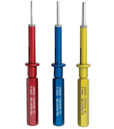
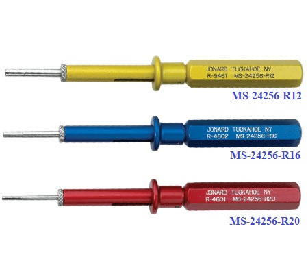
What does the positioner do and what are the colored pin tools pictured above for?
Posted: Sat Mar 13, 2021 5:32 pm
by RonD2
Good purchase! Sooner or later, everybody maintaining one of these military vehicles needs one.
The 3 different colored positioners ("pin tools") are for different gauge wire and crimp terminals, indicated by the -12, -16, and -20 after the MS3191 part number.....12-gauge, 16 gauge, and 20 gauge. Typically, the -12 is good for 12 and 14 gauge wire and terminals, the -16 is good for 16 and 18 gauge wire and terminals, and the -20 is good for 20 and 22 gauge wire and terminals.
As stated in Wes' photo, a positioner is used to automatically set proper crimp length and ratchet tension release (crimp) of the terminal to the wire. If you bought one without positioners then you'll do that manually. Not a big deal, so long as you use the correct size wire and terminal and don't over-crimp (crush) the terminal, which can make for a bad or weak electrical-mechanical connection and make assembly with the other connector parts difficult (especially when using Douglas connectors).
Are you using Douglas or Packard connectors?
It's debatable, but I always hit mine with a tiny bit of solder after crimping to seal the connection. Certainly not required, it just makes me feel better.
This might help you understand the tool:
https://www.aepint.nl/wp-content/upload ... MS3191.pdf
Good luck!
Posted: Sat Mar 13, 2021 9:42 pm
by wesk
what are the colored pin tools pictured above for?
The three long six sided handled tools are pin removal/insertion tools. The pins in the screw type connectors have small retaining tabs that keep the pin in the plug or socket stationary. There are many different size pins and many types of retention tabs so the pin remover/insertion tools also have different styles & shapes.
Posted: Sat Mar 13, 2021 11:09 pm
by RonD2
Thanks Wes.
Yes, pin insertion/removal tools and crimp tools are two very different tools.
I totally missed that he asked questions about two different tools in the same sentence...

I'd have to go check my tools, but recall that the industry standard color coding for wire gauge tools is that red is used for 12-14 gauge, blue is 16-18 gauge, and yellow is 20-22 gauge.
Posted: Sun Mar 14, 2021 1:06 am
by wesk
but recall that the industry standard color coding for wire gauge tools is that red is used for 12-14 gauge, blue is 16-18 gauge, and yellow is 20-22 gauge.
Take a closer look at the MS# on the handles!
Do you remember the color coding on the electrical solderless splices?
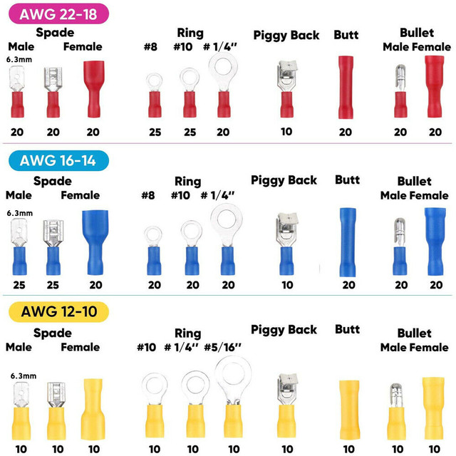
And the solderless terminals?
Posted: Sun Mar 14, 2021 7:52 am
by 4x4M38
Well heck.
I learned something again.
I had no idea there was a color standard.
Posted: Sun Mar 14, 2021 12:05 pm
by RonD2
And I got it back-a$$wards (again).
Need to look more before I leap.....my half-heimers (CRS half the time) is acting up again.
Posted: Mon Mar 15, 2021 8:41 am
by JeepdaddyRC
Seems the #12 wire is critical for correct/maximum voltage to the distributor - for that elusive blue spark.
Which option would result in the best repair and the least voltage drop?
1. An additional Douglas connector placed where the wire is currently severed (at screw connector at distributor). This option will add an additional connection between the ignition switch and distributor and an additional foot of total length.
2. A correctly spliced soldered connection using a modified M37 distributor wire from Midwest Military (pictured above). The Douglas connector could be removed and the screw terminal spliced/soldered into current #12 wire.
Posted: Mon Mar 15, 2021 9:28 am
by wesk
I do not waste my time with improvised substitutions and additions. I would simply remove the old wire from the switch to the distributor and build a new wire from the correct gauge mil spec wire using existing ends if they are serviceable or new terminal hardware with a crimper just like the guy in the motor pool would have done. And while you are fooling with the switch take an Ohmeter and determine if that switch has high resistance caused by internal corrosion of it's contacts.