Page 1 of 1

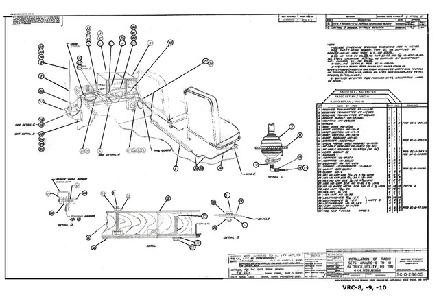
Receiver- Transmitter RT-68/GRC

Posted: Wed Jan 04, 2023 3:53 pm
by horse
Hi, I have the above unit in my Jeep with a PP-112/GR power supply mounted onto a MT-299/GR mount. For good weight distribution its behind the passenger seat.

The power supply lead is CX-2031A/U 8FT 3IN.

I have recently bought and mounted the Radio Receptical mounted by the side of the passenger seat. Mid West also supplied the male plug to fit into the Receptical from the Transmitter.

At the moment the power supply has a loop on the end of the positive ready to go onto a battery, the earth is just an open wire.

I have looked at many photos of these Transmitters power supply and that is how they are shown with the loop end on the terminals not connected into the Receptical.

I am correct in my thinking that the wiring should be soldered into the male connector and then into the Radio receptical, just the two wires each side?

I take it the loop end set up would be for just adding a power supply not using the Jeep batteries?

This is a whole new ball game to me as I only did a bit of Sideband on the C.B radios back in the 80ies. I do remember not to key the handset with no ariel connected.

Any thoughts would be appreciated.

Thanks.

Horse.

Posted: Wed Jan 04, 2023 8:01 pm
by wesk
Using the US Army Signal Corp Installation Drawing for the AN/VRC-10 setup the PS cable end at the right seat receptacle is installed to the male connector. Those connectors were set up for crimp type pins. You can use solder if you like but it's not a requirement.

Image
Here's the link to the full size file copy of this drawing: http://www.willysmjeeps.com/v2/modules. ... _photo.php

Here's the rear seat installation for the AN/VRC-10:

Image
Here's a link to the full size file for this photo: http://willysmjeeps.com/v2/modules/gall ... 10_aft.jpg

The male PS plug and the female PS receptacle at the pass seat have the details for installing their pins in TM 9-1825E Bendix/Scintilla electrical product maintenance manual.

Here's the crimper:
Image

Here's the pin remover/setters:
Image

Here's the manual:
Image

Chapter 5 is Bendix connectors:
Image

Posted: Thu Jan 05, 2023 7:46 am
by horse
Thank you Wes for a comprehensive reply.
Also good to know a different way rather than soldering.
Lots more to study.
Regards.
Horse

Posted: Fri Jan 06, 2023 4:13 pm
by horse
I am unable to find the TM 9-1825E Electrical Equipment in the Downloads or on your photo albums.
Am I missing something?
Horse.

Posted: Fri Jan 06, 2023 4:20 pm
by horse
Found it.

Posted: Sat Jan 07, 2023 4:31 pm
by horse
Managed to get the plug soldered in today and the connections are good.

For anybody doing this I found the A B C on the plug ends.

A = positive

B= Ground

C = I understand is a spare if any of the others go down in the field. Waiting for the correction on this.

Horse.

Posted: Sat Jan 07, 2023 5:32 pm
by RonD2
horse wrote:For anybody doing this I found the A B C on the plug ends.

A = positive

B= Ground

C = I understand is a spare if any of the others go down in the field. Waiting for the correction on this.

Horse.
Hi Horse,
Which diagram in the radio set manual did you find the pin-out key that A = 24V and B = Ground?

Posted: Sat Jan 07, 2023 11:28 pm
by wesk
Most likely here:

Image

In the drawing in my previous post SC-D-28605 VRC 8-10 installation the cord in question item 16 lists the drawing number SC-D-28372 in the remarks column.

Posted: Sun Jan 08, 2023 2:22 am
by horse
It would have been good if I had found the wiring diagram from Wes but I did not see that one.

The jeep is running well and I did not want to link up any power from the battery down to the Radio Receptical and cause other problems if I had got something wrong.

So with the Radio Receptical disconnected from the battery I put 12v down the positive lead from a separate battery to determine which was the live pin, which came out as A. There are only two wires on the radio power lead so that part was fine after checking nobody had switched the wires in the power unit.

Probably not the correct way of doing things but it got a result.

Horse.

Posted: Sun Jan 08, 2023 3:12 am
by wesk
Good job Horse! That must mean your radio power receptacle was wired already before you installed it coming with the two wires as an assembly.

Posted: Sun Jan 08, 2023 6:45 am
by horse
Yes correct. Just the radio side to get right.

The NOS set came fully assembled.

It is difficult to see on the plugs from the outside how they are wired with the pins so close together.

All good.

Horse.