Page 1 of 1
E-brake cable route and termination
Posted: Thu Jul 19, 2012 9:29 pm
by Bretto
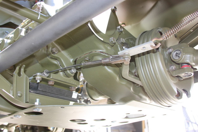
Is there a good illustration or does someone have some good pics of the routing and clamping of the ebrake cable? I think I have a good understanding of the cane and cowl end but not sure from the firewall to the business end. I have seen a few illustrations from the ord. but I can't figure it out from them.
I meant to take a look at yours Rick when I was at your place.
Thanks all!
Posted: Thu Jul 19, 2012 11:52 pm
by wesk
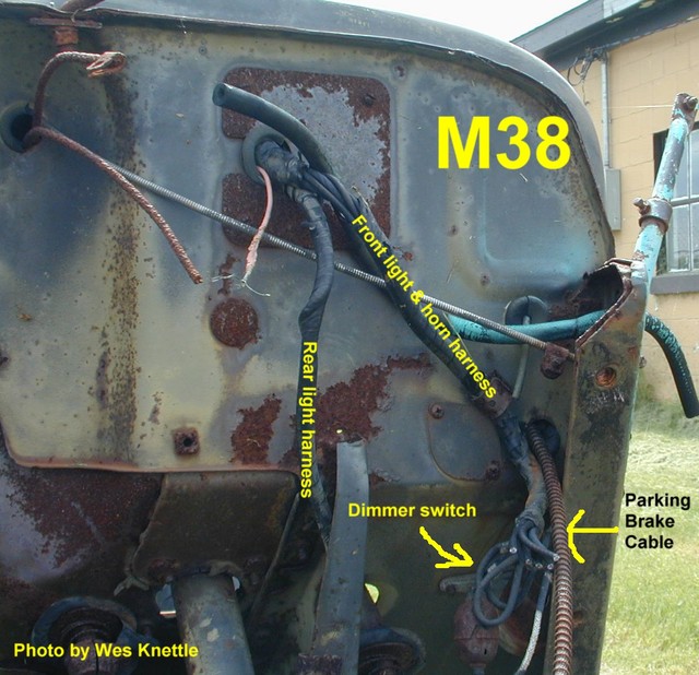
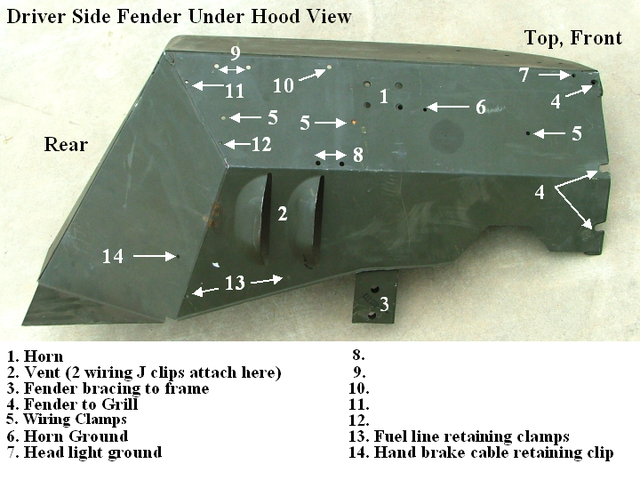
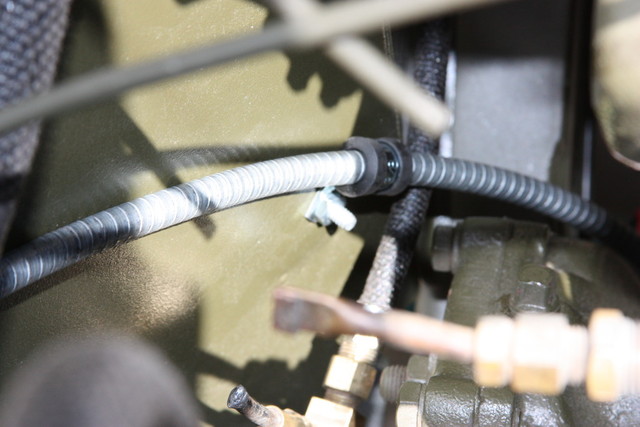
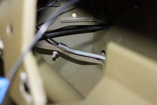
One clamp at # 14.
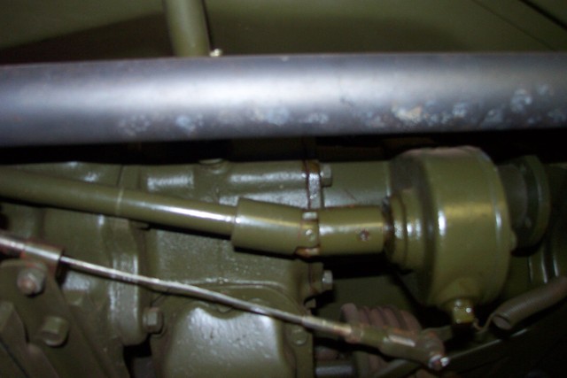
One clamp at tranny mount bracket. (PCO Rod)
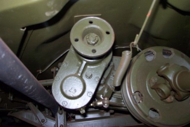
Spring to floor hump. (PCO Rod)
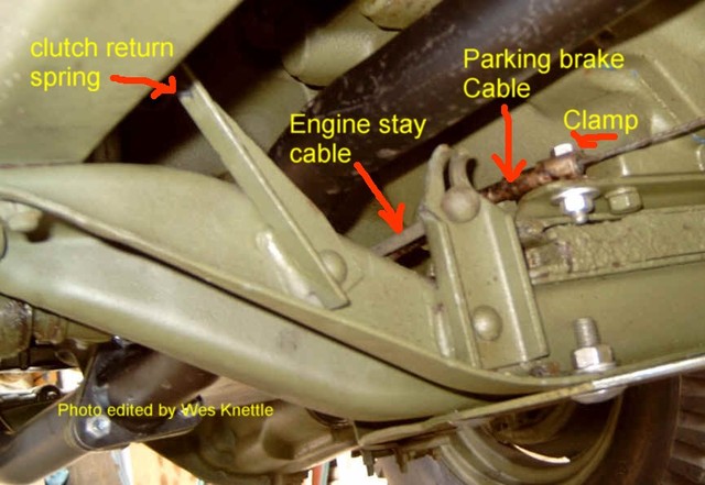
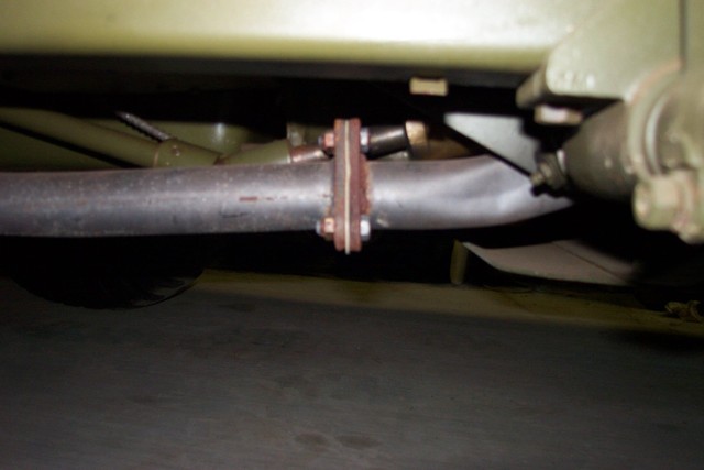
You can barely see the cable against the oil pan near the PTO shaft universal. (PCO Rod)
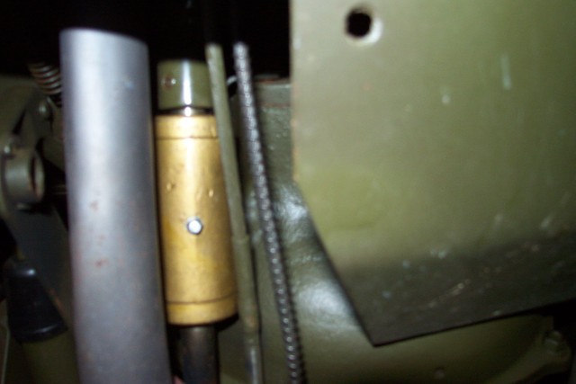
The cable next to the bell housing. (PCO Rod)
Posted: Fri Jul 20, 2012 10:40 am
by Bretto
Thanks Wes, gives me some direction. Is the clamp at the fender a hard clap or floating?
Posted: Fri Jul 20, 2012 11:02 pm
by wesk
Nor sure what you are asking. It is a clamp that retains the cable at the fender.
Posted: Sat Jul 21, 2012 6:29 am
by Bretto
Does it clamp the cable down solid or is the clamp more of a loop that keeps it agains the fender but allows movement.
Posted: Sat Jul 21, 2012 9:15 am
by wesk
If you look at fig 12 and 101 in TM 9-1804B you can see the cable at the fender and the steering box area. I don't recall a lot of movement on any of the three clamps.
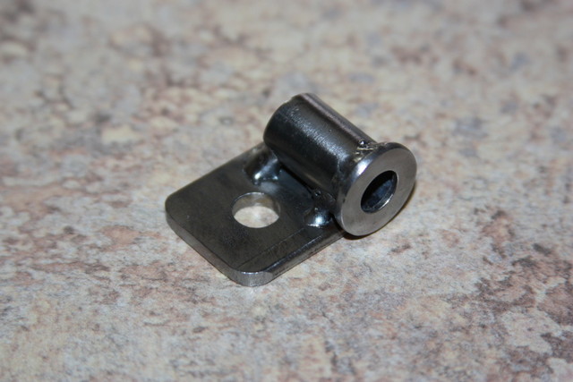
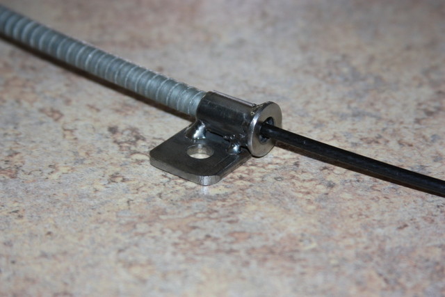
Here's the technical info on the clamp:
National Stock Number:
5340-00-704-7998
Federal Supply Class:
5340
National Item Identification Number:
007047998
Description:
STRAP,RETAINING
Detail:
A preformed item of rigid or semirigid material designed to partially surround other items such as cable(s), conduit(s), pipe(s), tube(s), or rod(s) or to completely surround them by means of a bridge strap(s) (which does not tightly clamp against the complete periphery). It is designed to retain and/or position the items close to a structure. It may be fastened to the structure on one end, both ends, or in the center. See also CLAMP, LOOP. Excludes BRACKET, PIPE; STRAP, LEATHER and STRAP, WEBBING.
Manufacturer Information:
7047998 19207 U S ARMY TANK AUTOMOTIVE COMMAND AMSTA-IM-MM
A5449 34623 AM GENERAL LLC
GPW14560 23040 FORD MOTOR CO FORD PARTS AND SERVICE DIV GOVERNMENT PART SALES
GPW14560 57526 FORD MOTOR CO
GPW2281 23040 FORD MOTOR CO FORD PARTS AND SERVICE DIV GOVERNMENT PART SALES
GPW2281 57526 FORD MOTOR CO
Techincal Specification:
CENTER TO CENTER DISTANCE BETWEEN ARCH AND MOUNTING HOLE ANY ACCEPTABLE
MOUNTING PAD NOT INCLUDED
OVERALL WIDTH 0.500 INCHES NOMINAL
CUSHION NOT INCLUDED
OVERALL LENGTH ANY ACCEPTABLE
MATERIAL THICKNESS 0.030 INCHES NOMINAL
MOUNTING HOLE SIZE 0.219 INCHES NOMINAL
SPECIAL FEATURES SLOT ON OPPOSITE END,0.219 IN. BY 0.312 IN.
INSIDE DIAMETER/ARCH LENGTH 0.313 INCHES NOMINAL
MATERIAL STEEL, QQ-S-698, COND CRPQ OR STEEL,QQ-S-698,COND HRPQ
STYLE DESIGNATOR U
Posted: Sat Jul 21, 2012 5:08 pm
by Bretto
Posted: Sat Jul 21, 2012 8:32 pm
by wesk
Nice job!

Posted: Sat Jul 21, 2012 11:00 pm
by Bretto
Thanks Wes.
The cable is about an inch too long. As it sits right now, the end of the adjustment rod is almost touching the brake arm. I think it will be fine though, I still have enough throw at then cane. Otherwise I will have to cut the rod if it stretches a lot.