Page 1 of 2
Installing distributor
Posted: Tue Apr 30, 2013 7:28 pm
by bl5211a
How about some quick feedback on best way to install distributor?
Posted: Tue Apr 30, 2013 8:32 pm
by wilfreeman
Get engine on TDC - cyl 1. Point rotor at #1 post. Slide distributor in. Rotate distributor to adjust point gap.
Posted: Wed May 01, 2013 12:00 am
by wesk
I have to ask.
Was it running ok and you pulled the distributor and want to put it back in?
Was the engine just assembled and you want to install the distributor?
I have a short guide to use for #1 (If you have an improperly indexed oil pump that forces you to install #1 plug wire on a position other then the manual specifies then now is the time to correct it. Many will tell you it will work just fine that way. That's true to a point. That point is when you no longer have enough swing to adjust the timing. Modern fuels will allow you to run a little more advance then the original 5 BTDC spec. 8 to 10 BTDC works quite well.
http://willysmjeeps.com/downloads/M38A1Timing.pdf
#2 reply will necessitate proper indexing of the oil pump.
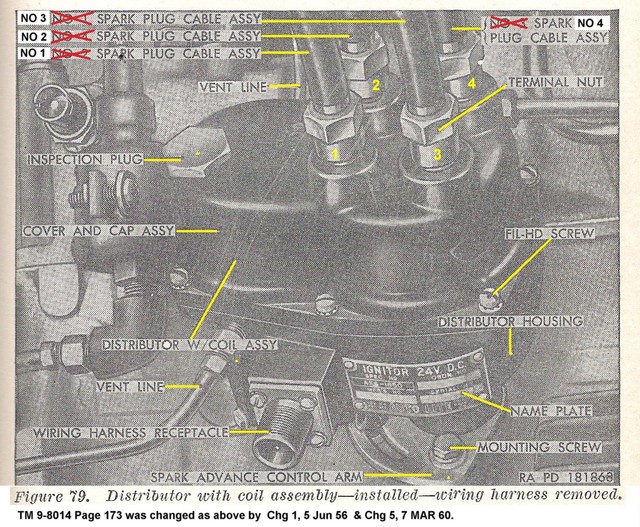
Be careful which illustration you use to determine the correct position for #1 wire. The fig on page 173 of TM 9-8014 for the Operation & Maint. of the M38A1/M170 was wrong and it was changed later by the Army.
Posted: Wed May 01, 2013 5:34 am
by bl5211a
Hello:
Thanks for the feedback. It is a 1955 M170 that just came back from machine shop. Shop indicated they indexed pump to manual that i gave them.
So I my response is #2.
Brian
Posted: Wed May 01, 2013 7:56 am
by wesk
If he did it correctly then start on the linked sheet by getting #1 TDC on compression then back off to the 5 Deg BTDC mark on the crank pulley. Slip the distributor in (the shaft can only engage in one position relative to the oil pump) and confirm the rotor is pointed towards the #1 plug wire terminal.
To prevent removal problems later be sure to smear a wee bit of anti-seize compound to the body of the distributor that fits snugly in the block and a wee bit on the bottom surface that slides on the lock down plate when you are adjusting it.
Posted: Wed May 01, 2013 10:36 am
by Hawkshadow
Sorry to jump in, but I've been reading through the other forums which came up in a search for "indexing." How do I find this 5 Deg BTDC Mark?
Posted: Wed May 01, 2013 10:53 am
by RICKG
Hawkshadow wrote:Sorry to jump in, but I've been reading through the other forums which came up in a search for "indexing." How do I find this 5 Deg BTDC Mark?
Check pg2 of wes's photo album, Ign sys L&F 134, Timing.
Photos of several variations for reference.
Posted: Wed May 01, 2013 11:26 am
by wesk
It is marked on the flywheel next to the TDC mark on early L134's and on the crank pulley or timing gear cover on later L134's and all F134's.
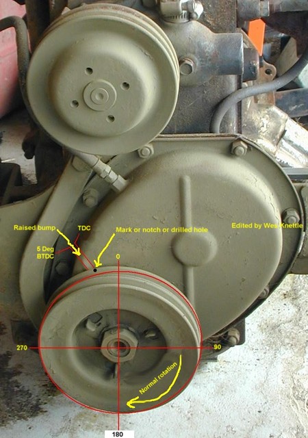
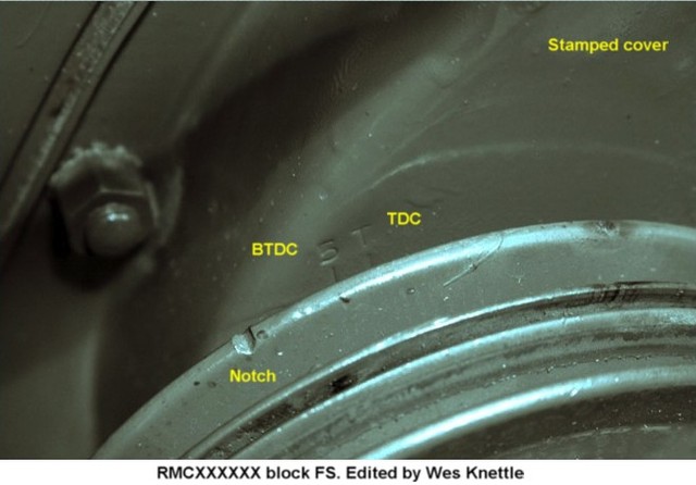
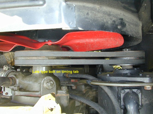
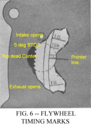
These marks may have varying nomenclatures on the various production flywheels.
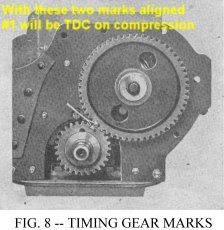
This is where the whole timing issue starts. If you do not have the external pulley/flywheel marks then this is the most accurate way to get TDC. Then you must use a degree wheel attached to the lower crank pulley to back the engine up exactly 5 degrees.
Rocking the piston with the finger / air pressure method gets you close to TDC but the crank can rotate 3 to 4 degrees with #1 piston at the top and making no visible movement or measurable movement of the piston. To resolve this dead angle problem a dial indicator riding on the piston can give you the start of movement on each side of the dead angle and then you can split the difference and make yoiur timing mark for TDC on your crank pulley or timing gear cover.
Posted: Wed May 01, 2013 6:44 pm
by bl5211a
hello Wes;
Mine is late style tab, with notch in pulley
http://www.willysmjeeps.com/v2/modules. ... _photo.php
[/url]
Posted: Mon May 06, 2013 10:36 pm
by Hawkshadow
Mine has 2 notches and no stamped indicators on the side... Any idea which notch is the right one?

Posted: Mon May 06, 2013 11:04 pm
by wilfreeman
I think the "v" notch is the timing mark, not the square notch. The TDC and 5° BTDC are stamped on the timing cover as in Wes' picture above.
Posted: Tue May 07, 2013 11:20 am
by wesk
Hawkshadow,
Both notches are unreliable since their origin is unknown. That pulley may have been marked by someone in the past and was used on a different engine by him and now it's on your engine. What reference point is on your cover that these pulley marks are suppose to reference to?
Too many unknowns. The only safe bet is to determine TDC by either using a dial indicator to measure #1 piston travel to pin point TDC on compression or remove the front timing cover and align the valve timing marks on both gears then re-install cover and pulley and make permanent marking on pulley and cover for TDC. Then install a degree wheel on the pulley and mark the 5 and 10 degrees BTDC marks on the pulley or cover (whichever side you are using for reference). I say 5 and 10 marks because from now on you will time for best idle between those two marks using modern fuels.
Posted: Tue May 07, 2013 4:10 pm
by Hawkshadow
Thanks for the input all. I checked today and it appears that the V notch lines up with what is labelled as the "raised bump" when #1 is TDC. Going from that, I can use that mark as 0deg and make another 5deg counterclockwise on the pully, correct?
Posted: Tue May 07, 2013 5:50 pm
by wesk
I doubt anyone wants to say yes to your question. Since none of us nor you have any idea where that mark came from, who put it there, was the pulley original to your engine and the questions can go on. As I have already posted. Verify, always verify things that have a lot assumptions placed on their accuracy. Prolonged ops to retarded can result in overheating and prolonged ops too advanced can result in spark knock (pinging) and it's resulting damage. It is a lot safer to verify TDC by piston position within 1/2 of a degree using the dial indicator method or the gear mark method and start with a known accurate figure for TDC. Anything else and you may as well ignore the marks completely and time it by ear, vacuum or RPM and at be as close or closer.
Posted: Tue May 07, 2013 9:02 pm
by Hawkshadow
Sorry, I should have been more specific. I still have the head off of the unit and verified that when #1 Cyl is at the top of its stroke, the notch is at the raised bump.