Igntiion switch testing
Posted: Wed Jul 23, 2014 8:56 am
4x4m38 asked this question so I am sharing it here in the spirit of information sharing this site is set up for.
A word of caution, you should understand that a wiring diagram lays wires out so they make sense or logic as to their purpose and route. The wiring diagram does not show the physical arrangement of the wires or connector.
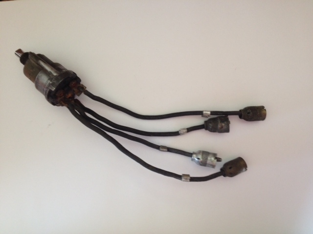
My answer:I bought an ignition switch on Ebay with Douglas connectors. The wire insulation is surprisingly resilient and in decent shape. It looks like there was resin or some sort of epoxy material which enclosed the connections on the back of the switch. It was badly cracked and split in may places. I was able to take a pair of water pump pliers and apply pressure, splitting and cracking the insulation material further, which allowed me to get it all off.
The terminals and soldering on the wires is tight, with no corrosion, other than some light surface rust which should be able to be cleaned off with a wire brush or something. I know there is a pinout on one of the pages here for the headlight switch and hopefully the ignition switch as well.
My question is what would I go back with to reinsulate the terminal connections when I get to that point? Do I just make a round container a little larger than the switch and contacts and pour it full of epoxy?
Brian,
The failed potting compound is common to very old switches. Sometimes cleaning up and re-potting works fine. Sometimes not. Risk is 50/50.
The compound you choose is up to you and your preference in materials and colors. Just google it:
https://www.google.com/webhp?source=sea ... g+compound
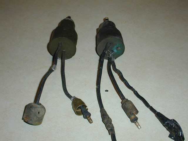
Most Douglas connector switches only have two or three wires.
2 Wire switch
Using a digital ohm meter test the switch for internal shorts.
With switch off check across the two leads for continuity. Should be none.
Then check each lead to the switch's metal housing for continuity. Should be none.
Now turn the switch on and repeat the tests above.
The two leads should now show continuity.
There should not be continuity between either lead and the switch housing.
3 Wire switch
With switch off check across the three wires in pairs (two at a time for continuity. Takes three separate readings. There should be no continuity between one lead and the other two but the other two should have continuity. (the two leads which share continuity are then labeled 12 (ignition) & 86 (accessory)
Check each lead for continuity to the switch's metal housing. Should be none.
With switch on all three wires should share continuity but should not show any continuity with the switch housing.
A word of caution, you should understand that a wiring diagram lays wires out so they make sense or logic as to their purpose and route. The wiring diagram does not show the physical arrangement of the wires or connector.