Page 1 of 1
Electric Fuel Pump and Vacuum Lines
Posted: Tue Feb 10, 2015 9:49 pm
by cjohle
Hello All - My '53 M38A1 had an electric fuel pump installed when I purchased it. It runs fine (maybe a little rich), but after I was looking around at the air cleaner I noticed the the horn that fits on the carb is all Bubba'd up (not the correct horn either).
I'm trying to figure out where all of the vacuum lines should run if you have an electric fuel pump instead of the manual one with vacuum. I'm nearly positive it isn't correct in its current configuration. I'd be happy to send pics/descriptions if it would help. My main concern at this time is that the hose that goes from the oil fill tube to the valve cover doesn't go to the valve cover. It doesn't go anywhere - its just cut. The hose from the valve cover goes down to the passengers side of the crank case (PCV valve?).
I realize I have no vacuum for the fording system, but I'm really concerned about the pressure relief in the crank case...
Any help would be greatly appreciated!
-Casey
Posted: Tue Feb 10, 2015 10:45 pm
by wesk
Why not just post photos here for us to view and then we can answer you here and all can benefit from the entire discussion?
When you say horn on the carb I assume you are referring to what is usually called the carb air horn.
Here's your album:
http://www.willysmjeeps.com/v2/modules. ... _album.php
Here's the rules.
http://www.willysmjeeps.com/v2/modules. ... opic&t=498
Here's the tutorial for loading your album:
http://www.willysmjeeps.com/v2/modules. ... _album.php
Here's the tutorial for posting your photos:
http://www.willysmjeeps.com/v2/modules. ... pic&t=8670
Posted: Wed Feb 11, 2015 3:47 pm
by cjohle
OK, I'll take some pics when I get home and post them this evening.
Posted: Wed Feb 11, 2015 6:36 pm
by cjohle
OK here we go.
The shows the hose running out of the valve cover over the top of the oil filter
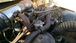
This is where the hose attached to the passenger's side of the engine

Here you can see the hose that should go from the oil filler tube to the top of the valve cover.

This is a picture of the air horn that connects to the carb. Notice the bailing wire? Its the wrong horn and has been modified.

Posted: Wed Feb 11, 2015 7:51 pm
by cjohle
I also posted more pics in my album if anyone is interested. The folks that had it before me did some cool functional things and some things that still have me scratching my head...
Posted: Wed Feb 11, 2015 7:58 pm
by wesk
1- It's the wrong carb as well.
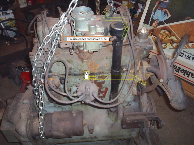
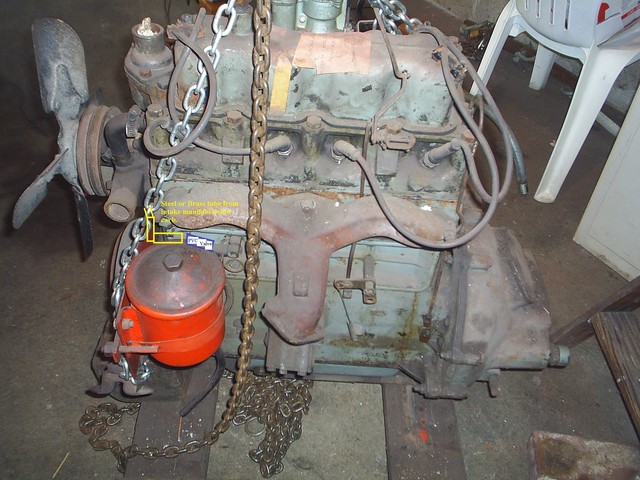
Run a hose from your crossover pipe to one side of the oil filler pipe. Run another hose from the other side of the oil filler pipe to the 90 Deg fitting on the valve cover. Now run a steel or brass tube from the intake manifold hole below the carb to the PCV valve which should be attached to the valve lifter access cover on the driver's side of the block.
Here are two crude illustrations. I leave the connection fittings up to you.
Posted: Wed Feb 11, 2015 11:58 pm
by cjohle
Awesome! Thanks so much for the info. So this would be the PCV valve?
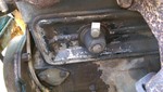
And what does the the intake manifold do? I guess I'm confused as to why that would be connected to the PCV.
Is there any reason I can't run a hose as opposed to a brass or metal pipe?
And lasty, is the current configuration potentially causing issues with my engine? As in, should I refrain from driving it before I get things moved around?
Again, I really appreciate the help.
Posted: Thu Feb 12, 2015 12:34 am
by wesk
No that is the adapter to which the PCV valve fastens to on the M38 & M38A1. In the first photo I posted look closely above the fuel pump. What you see from left to right is: #1 90 Deg brass fitting connects tube from intake manifold to the #2 PCV valve then #3 a hose connects PCV valve to fitting on #4 the adapter. You can also mount the valve directly to the intake manifold and run the tube to that adapter. Tube is better idea than hose for several reasons. Original was steel tube. Tube can handle the heat around the exhaust manifold. Tube is safer passing around the front of the engine with the spinning pulleys, belts and fan.
Positive Crankcase Ventilation (PCV) needs a positive movement of air. This is accomplished by having the engine intake manifold suck the air from the crankcase during certain periods of operation to ensure pollutants are recycled inside the combustion chambers.
The pipe at the intake does the sucking through the PCV valve on the driver's side of the engine. Those fumes in the crankcase will then move from the crankcase, through the PCV valve to the intake and get reburned.
The two hoses on top make sure filtered air is returned to the crankcase.
Your engine as configured now does not have Positive Crankcase Ventilation.

Go to Binkey's Page and click on "Repair Info" then Click on "PCV Valve"
http://home.comcast.net/~sday77/binky/index.htm
Posted: Thu Feb 12, 2015 7:33 am
by cjohle
OK, that makes sense. You've penetrated my thick skull, no minor feat!
Posted: Fri Feb 13, 2015 9:08 am
by cjohle
Thanks for the help, Wes. I got it all hooked up last night. I used flex line as a temporary solution as I have to drive it this weekend. I'll get the steel line asap. I still need a flare tool.
There was already a PCV valve so I just used the old one as I don't know what pressure it should be. Just to be sure, the pressure should be restricted going into the intake manifold, correct?
It seems the gas smell from the exhaust isn't as strong and its a little bit of a different smell. I'm assuming this should be the case...
After the steel line its onto fixing the play in the steering pitman arm (new bushing and seal and fix the original horn while I'm at it). I'm crossing my fingers that I don't need a new worm shaft or pitman shaft.
Posted: Fri Feb 13, 2015 11:47 am
by wesk
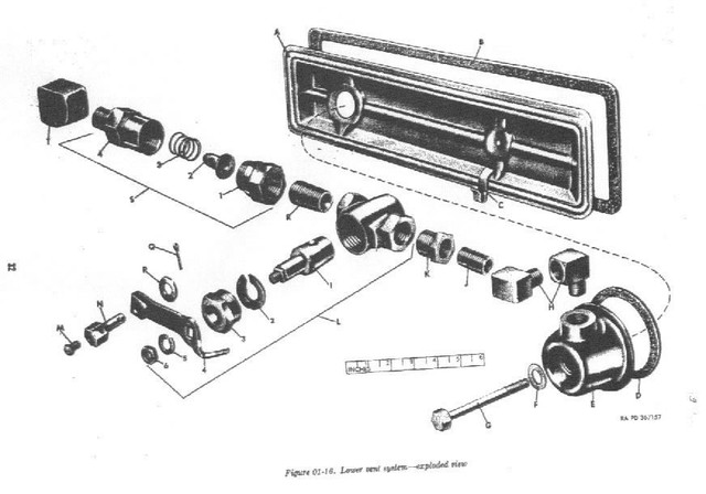
This is the layout of a stock early M38A1 with the fording vent system installed. The later 1953/54 & up without the fording vent system will replace Assembly "L" and part "K" with a short piece of rubber hose.
Your correct direction od installation for your PCV valve (Item assembly "S") is as show with the short end housing (part "1") away from the intake manifold.
Be sure to use the Ross steering gear box overhaul manual along with your TM 9-8015-2 when rebuilding it.
http://www.willysmjeeps.com/v2/modules. ... it&lid=136