Picture is worth a thousand words. Post a PIC or two of what you are looking at so we can see the same thing. ID the PN of the steering box you are working on. Or at least post the casting number on the box. _________________ Wes K
45 MB, 51 M38, 54 M37, 66 M101A1, 60 CJ5, 76 DJ5D, 47Bantam T3-C & 5? M100
The original adapters were constructed with a flared tube end that crimped it into the threaded adapter. Lousy design actually. They did not seal tight and allowed the gear oil to get into the switch which it was actually built to do. The ones we make are a one piece design so that the tube cannot leak oil into the switch. The photos in the ORD 9 show some individual pieces that were actually assemblies. Take the worm on the end of the shaft. They do not come apart, yet they are shown as separate pieces in the book.
John
Joined: May 30, 2014 Posts: 3447 Location: Texas Hill Country
Posted: Mon Nov 13, 2017 7:44 am Post subject:
Good morning John,
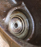
Yes the piece remaining in the adapter is slightly loose, but looks
like it was crimped or flared at the bottom.
I'm a little confused. Was the switch designed to get oil into it? That's
what I'm reading from your post.
Save buying a new adapter with tube, is there a fix? Is it terminal to
run it with the tube loose or removed entirely?
Yes, the Ord 9 G758 in this example as well as the G740 shows individual parts that were included in assemblies in the delivered vehicles. Good point.
That tab on the spare carrier comes to mind.
The switch was not designed to have oil get to it. Hence the crimped tube and that goes up above the oil level. You can try to solder the tube to the disc in the center. I have done this but not very successfully.
John
Joined: May 30, 2014 Posts: 3447 Location: Texas Hill Country
Posted: Mon Nov 13, 2017 10:25 pm Post subject:
Hello Wes,
My camera is full and I need to dump it before I can take any more photos.
But I will and post.
John, I don't see a disc. The tube is flared at the bottom. The adapter has
a loose bit that looks like the same material as the tube. It appears
to be crimped at the top and bottom of the adapter.
I can see where the flared portion of the tube may have been soldered to the
top crimped part. It would make more sense if the whole tube had a flare that sat on top of the adapter and the rest went on through and was crimped at the bottom. It just looks like two pieces. Could it have been twisted in two?
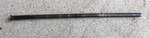
It appears the tube may have been attached to the bit still in the plug (adapter) and broke off somehow. In the Ord 9 G758 image of the parts the tube appears flared at the bottom like a trumpet. It would make sense to me that it was swaged at the bottom below the trumpet area, which would allow one to flare and peen the lower portion, sort of sealing it to the plug or adapter.
However, the fact that there is a rubber seal at the top of the switch assembly makes me think the designers did not rely on the tube, oil seal, to keep oil out of the switch, and that it was basically a guide for the horn rod. The portion still in the plug or adapter is slightly loose and can be rotated. Whether it got that way through age and abuse is a possibility, but maybe it was never meant to be liquid tight. It just does not seem to be robust enough an assembly to stand much moving around, especially during maintenance. I'd certainly entertain thoughts on either side.
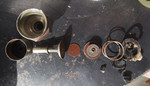
The horn switch did not work. I figured it was a good time to see what fails in these things. During disassembly, similar to removing the bezels on gauges, the plastic like material holding the pins and what was crimped into the switch housing fell apart. Not micarta, I can't remember the name.
It did not look cracked, but probably was. Or I broke it. Just mild corrosion on the inside of the switch. Everything still moved up and down.
There is a rubber seal that seals the shaft of the button and has a flat portion sitting on top of the assembly that seals the flat portion to the wall of the the plug (adapter). There was no oil below the seal.
The switch failed because the electrical connections were tarnished (not rusty, but just enough darkening of the metals to prevent contact).
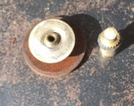
In the last photo you can see the disc and one of the two pins that make contact that I burnished with some 400 grit. The pins would have been connected to the wiring harness.
You cannot post new topics in this forum You cannot reply to topics in this forum You cannot edit your posts in this forum You cannot delete your posts in this forum You cannot vote in polls in this forum