How To: Fuel Pump Rebuild
Posted: Sat Apr 09, 2016 8:50 am
Welcome to a rebuild of your dual action fuel pump. With some dedicated time and concentration, this is a fairly easy and enjoyable rebuild. Make sure that you have an open work space to set things out. I also suggest taking detailed pictures during disassembly for reference during assembly.
Admittedly it has now been a couple of years since I rebuilt my pump. I intended to write this article at the time, but it has been pointed out that I forgot. As such, if anyone sees any details that should be added, please let me know!
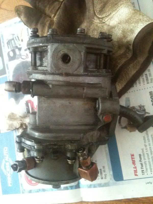
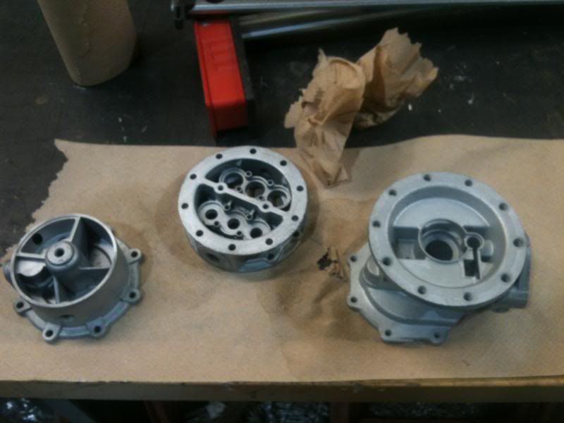
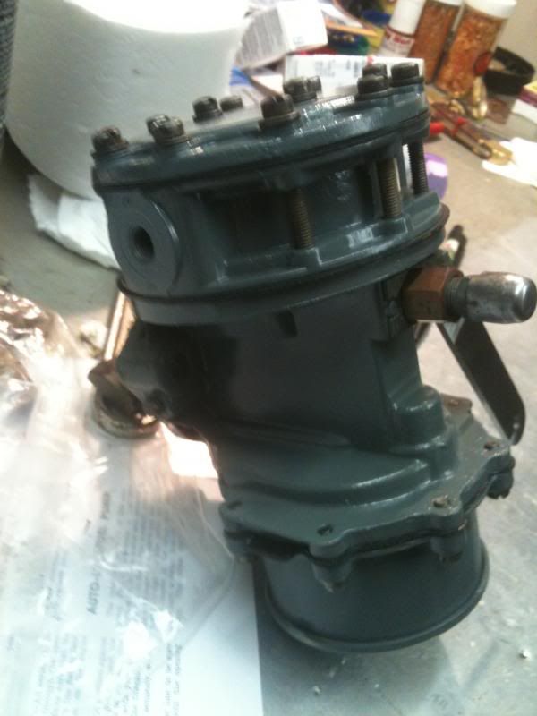
Before we begin. I will be referencing the dual action pump assembly in 3 pieces. There is the central body, with the fuel pump on top and the vacuum pump on the bottom.
Remove the pump, making sure that you do not loose the pump to engine spacer.
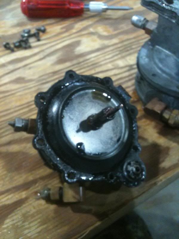
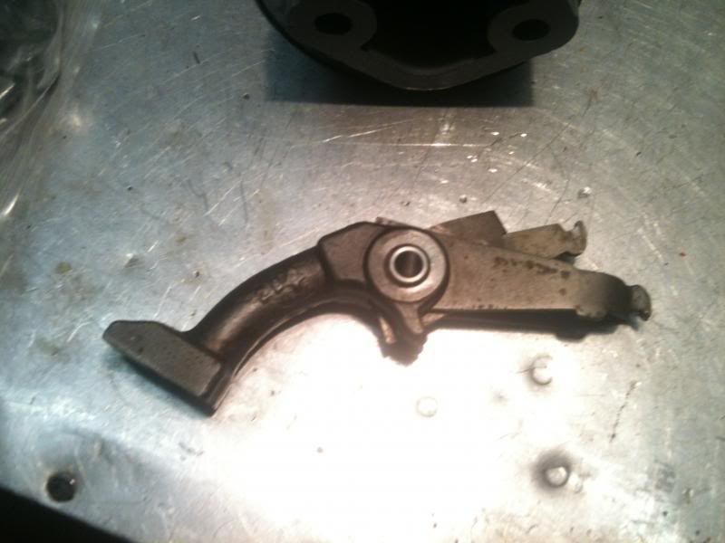
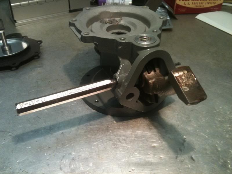
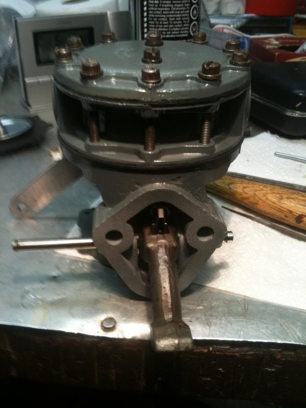
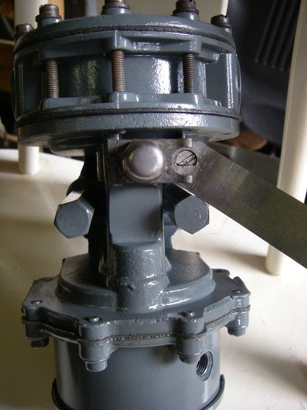
Take note of everything as you disassemble your pump. This picture shows how the arm sits.
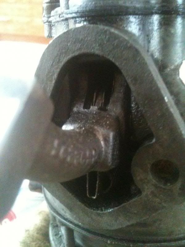
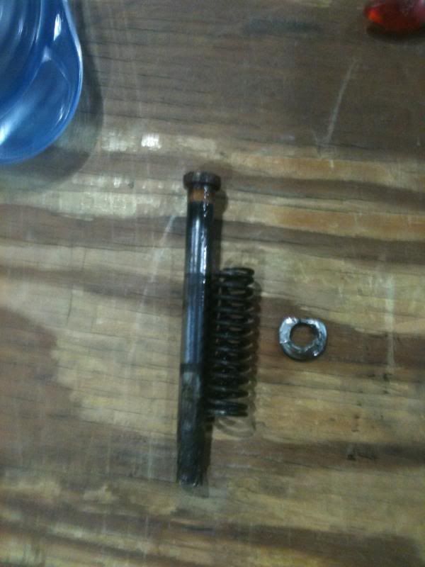
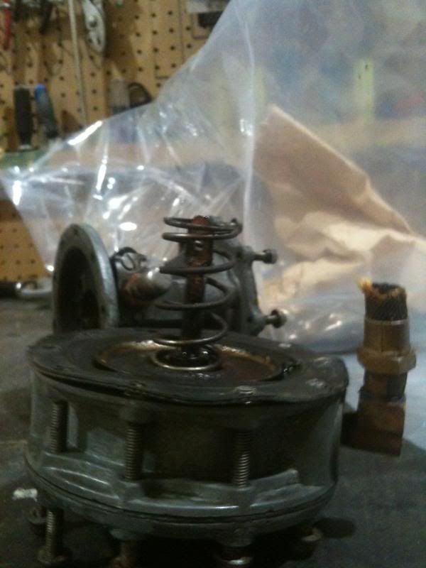
Remove the shaft that the arm hinges on. This will also release the arm's spring.
Remove the screws that hold the vacuum pump to the body.
Remove vacuum pump.
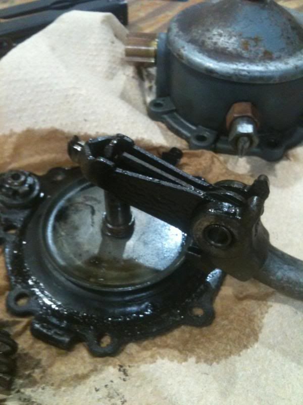
This is how the arm links in to the vacuum diaphragm arm.
Remove the fuel pump portion from the body.
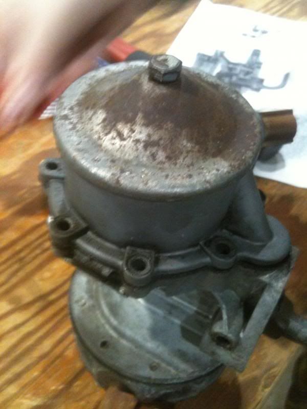
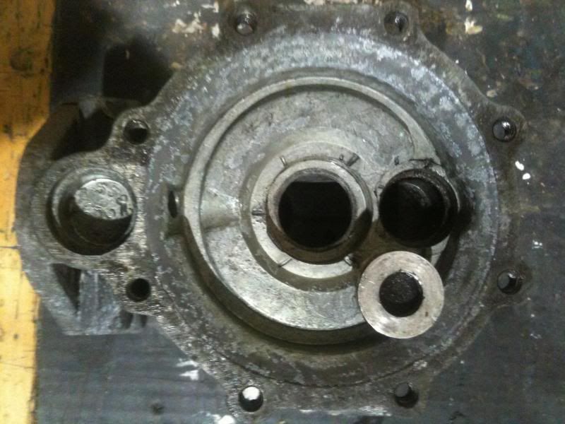
Main body.
You can see that on this pump, the vent line was capped with a breathable fitting similar to the ones on the axles.
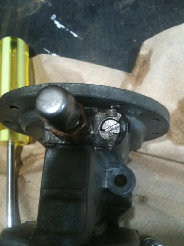
Unscrew that fitting.
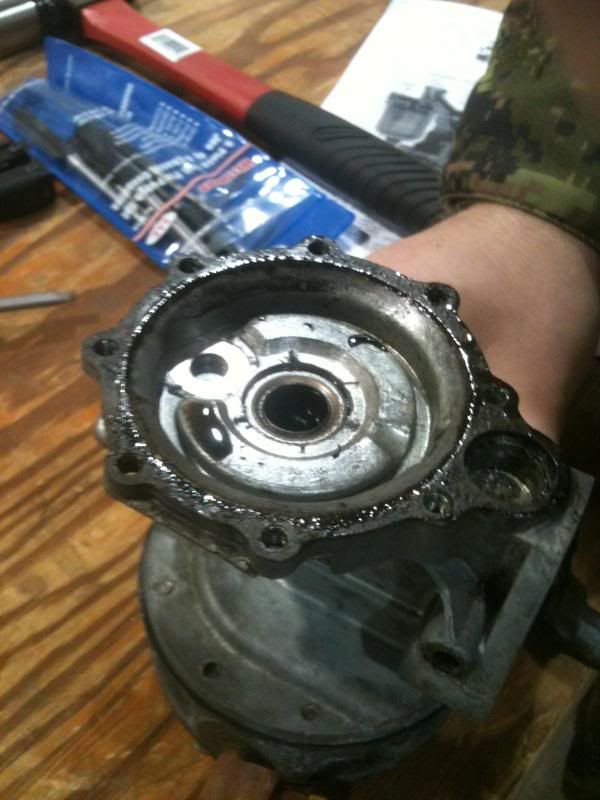
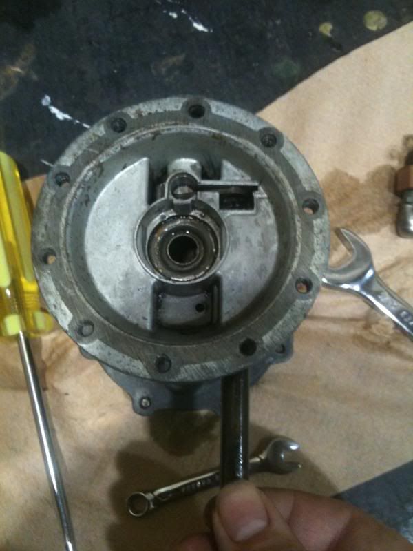
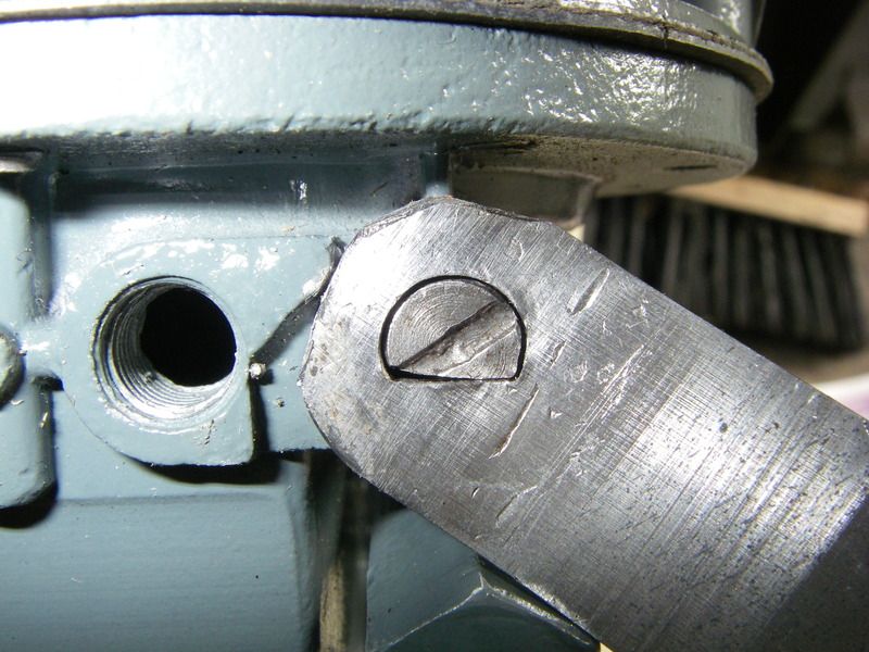
Remove the retaining plate. The metal piece that you see here keeps the shaft seated. It will be replaced by the primer arm during assembly.
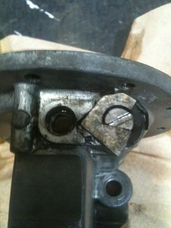
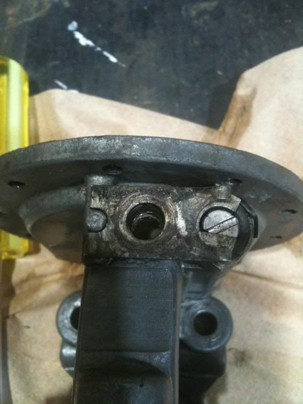
Remove and note the rubber o-ring next.
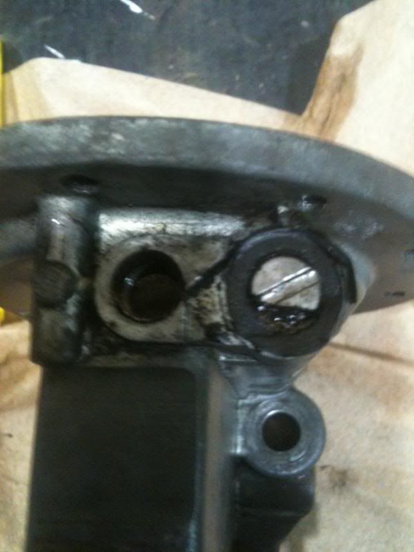
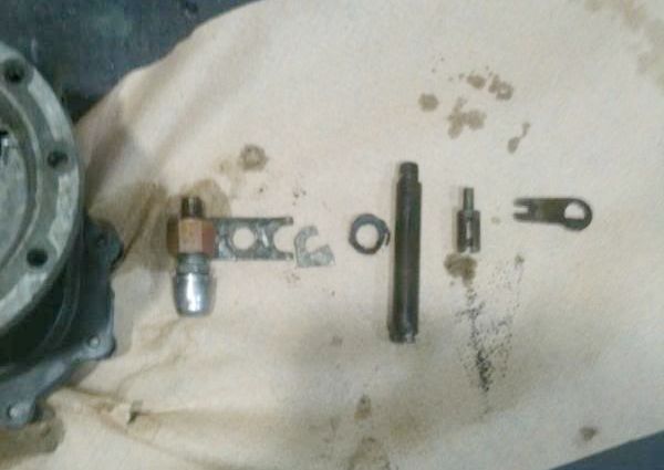
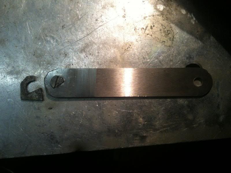
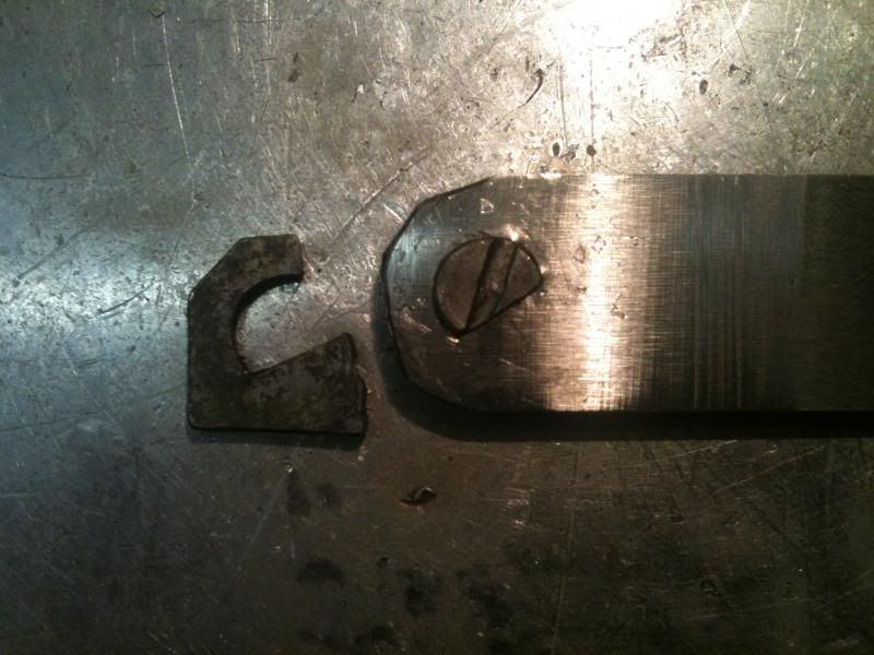
Remove the primer shaft. At the end of the primer shaft there is a link which goes across to across to a pin. This pin is what operates the diaphragm during priming.
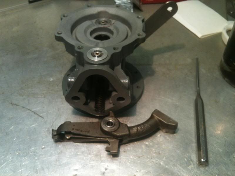
Here it is laid out. On the right you can see the link and pin referenced above.
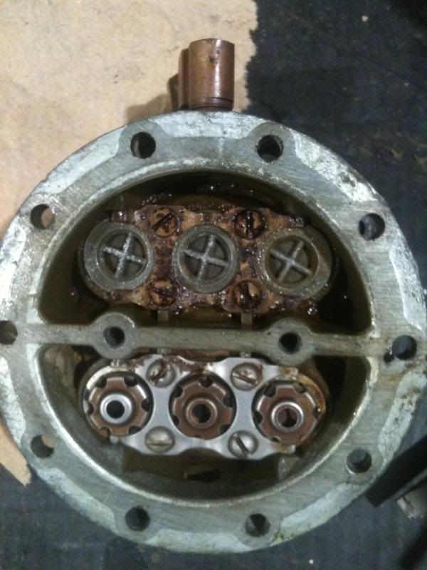
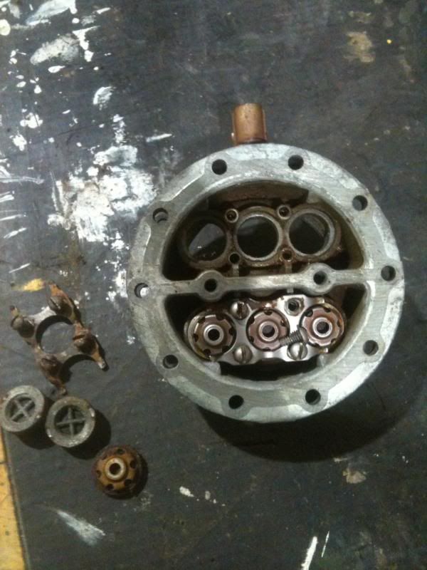
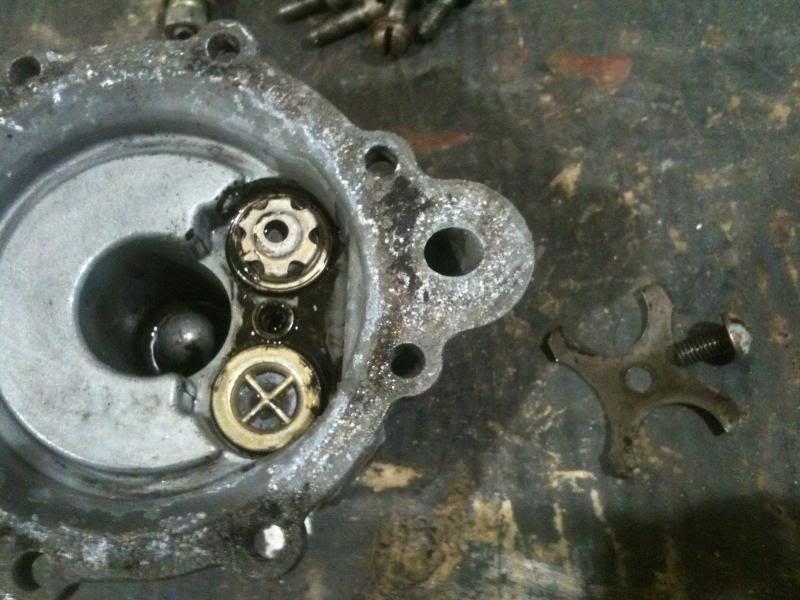
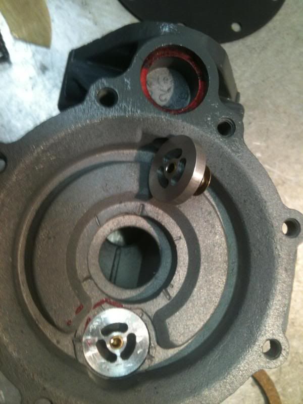
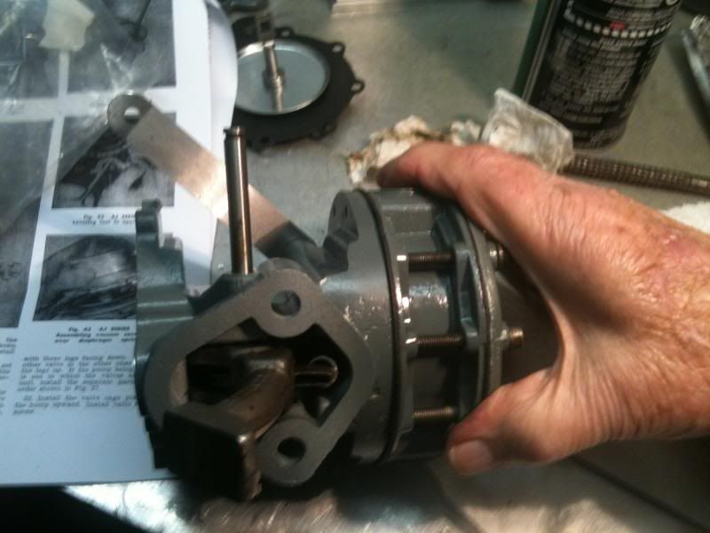
Returning to the fuel pump, remove the valves. Note the orientation of the valves in the pump!
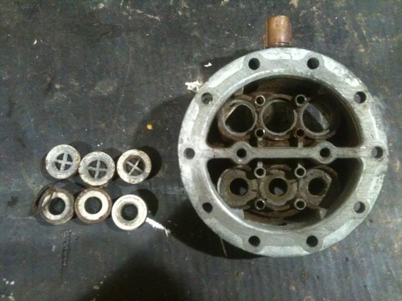
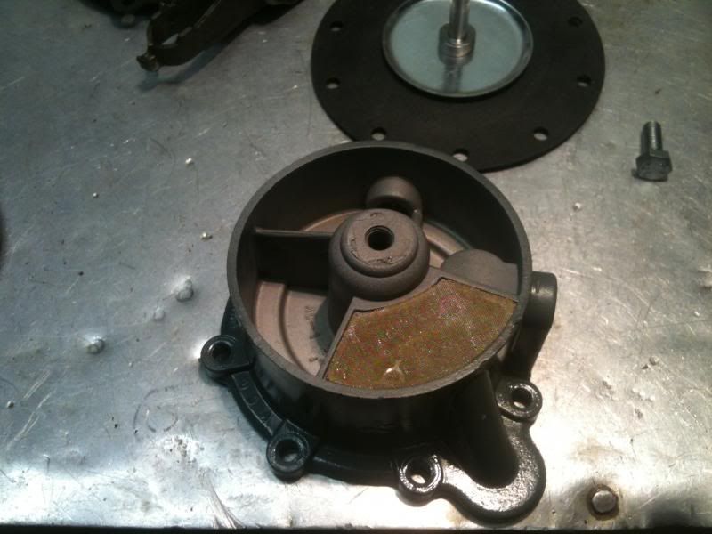
Remove the valves from the vacuum pump
Remove remaining components from the body.
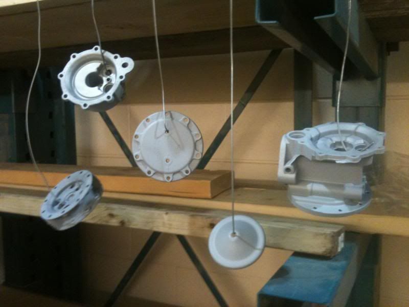
Clean the disassembled pieces as you see fit. After a sandblast to clean all of the deposits and any remaining bits of gasket, I chose to prime and paint my pump.
Assembly
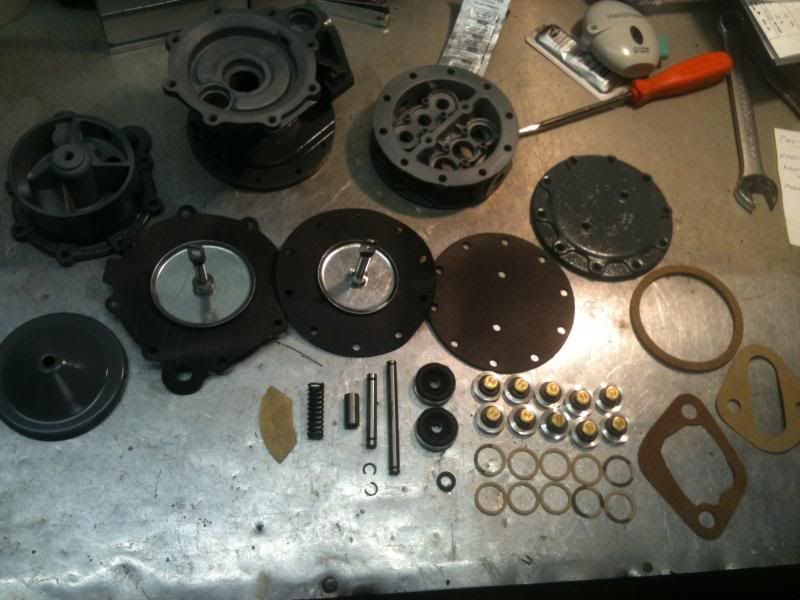
Here are all of the components from the rebuild kit supplied from Then and Now.
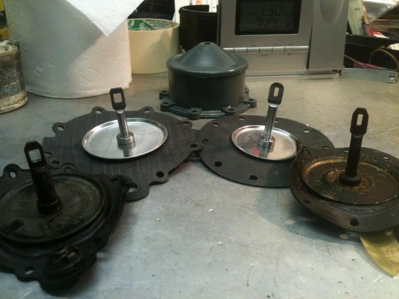
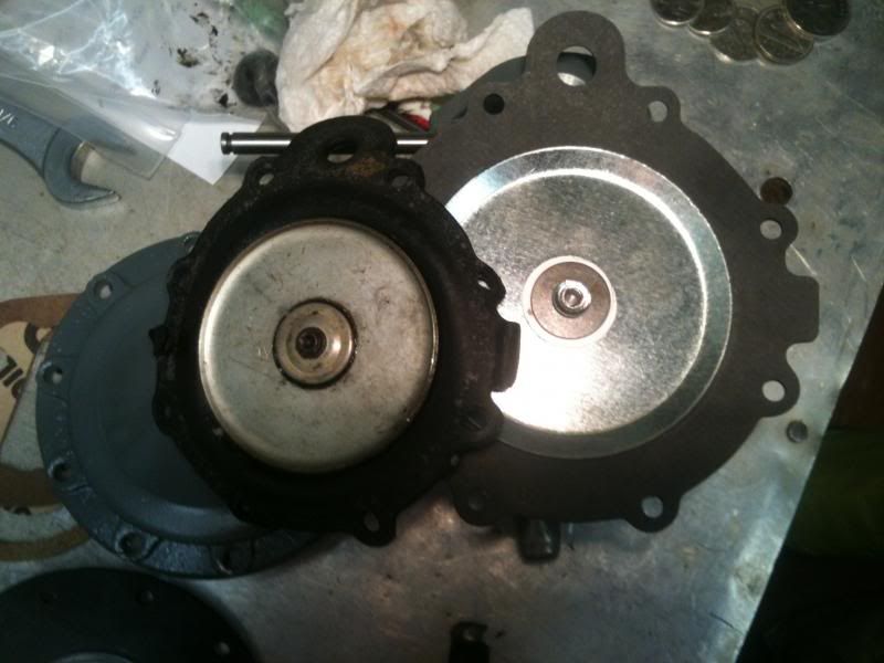
The old diaphragms beside the new. We will return to this comparison later.
Install the new gaskets and valves throughout. I used hi-tak to hold the gaskets in place during assembly.
Here you can see that there was a difference between the old and new vacuum diaphragms. I contacted Then and Now and they promptly shipped a replacement of the proper size.
This is the primer arm that arrived from Then and now. It required some fitting and shaping to work. Re-assemble the primer shaft and links in the order removed and install at this point.
Install the new bushing in the arm.
Install the new filter screen in the vacuum pump.
To install the arm, use a long thin punch in place of the pin during assembly.
Install the new fuel pump diaphragm, hooking the diaphragm shaft to the pump arms. Hooking the diaphragm shafts to the arms is a finicky task. Take your time.
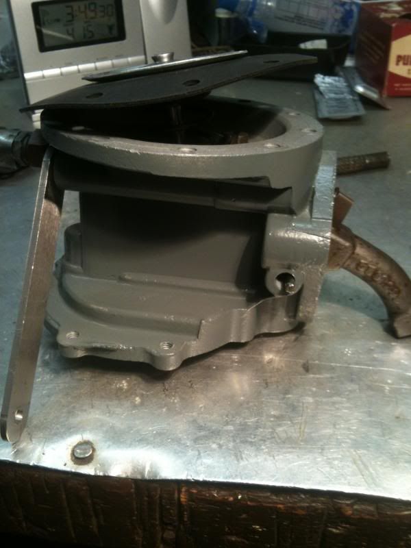
Install the pump housing.
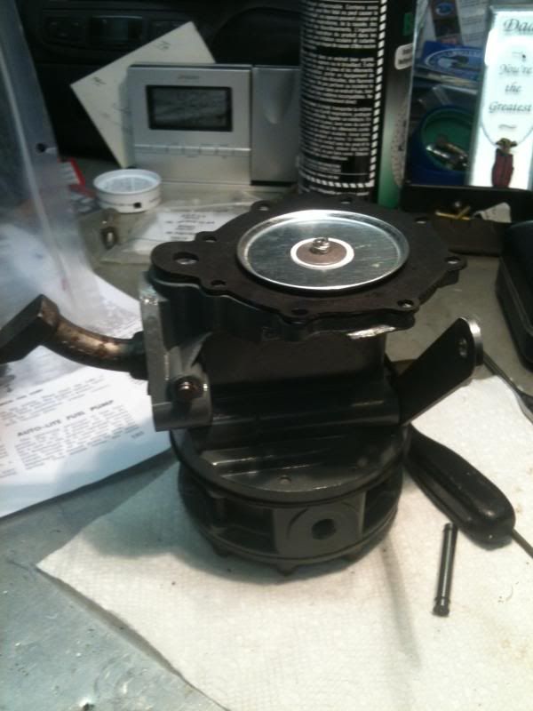
Install vacuum pump diaphragm.
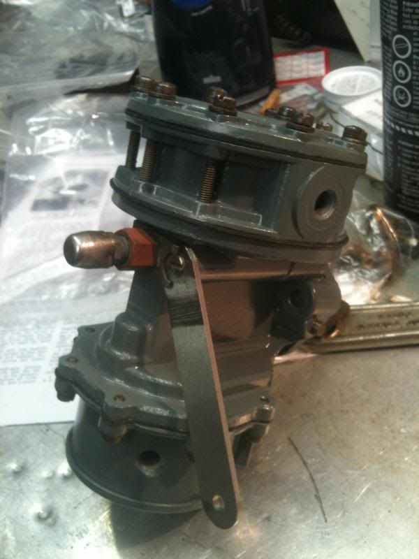
There you have it. Note that I did not make the forward bend in the primer handle when I initially did the rebuild. Ensure that you do this!
As mentioned at the beginning, it has been a couple of years since I completed this rebuild. If there is anything that I may have missed or forgotten in that time, please feel free to add it in!
Admittedly it has now been a couple of years since I rebuilt my pump. I intended to write this article at the time, but it has been pointed out that I forgot. As such, if anyone sees any details that should be added, please let me know!
Before we begin. I will be referencing the dual action pump assembly in 3 pieces. There is the central body, with the fuel pump on top and the vacuum pump on the bottom.
Remove the pump, making sure that you do not loose the pump to engine spacer.
Take note of everything as you disassemble your pump. This picture shows how the arm sits.
Remove the shaft that the arm hinges on. This will also release the arm's spring.
Remove the screws that hold the vacuum pump to the body.
Remove vacuum pump.
This is how the arm links in to the vacuum diaphragm arm.
Remove the fuel pump portion from the body.
Main body.
You can see that on this pump, the vent line was capped with a breathable fitting similar to the ones on the axles.
Unscrew that fitting.
Remove the retaining plate. The metal piece that you see here keeps the shaft seated. It will be replaced by the primer arm during assembly.
Remove and note the rubber o-ring next.
Remove the primer shaft. At the end of the primer shaft there is a link which goes across to across to a pin. This pin is what operates the diaphragm during priming.
Here it is laid out. On the right you can see the link and pin referenced above.
Returning to the fuel pump, remove the valves. Note the orientation of the valves in the pump!
Remove the valves from the vacuum pump
Remove remaining components from the body.
Clean the disassembled pieces as you see fit. After a sandblast to clean all of the deposits and any remaining bits of gasket, I chose to prime and paint my pump.
Assembly
Here are all of the components from the rebuild kit supplied from Then and Now.
The old diaphragms beside the new. We will return to this comparison later.
Install the new gaskets and valves throughout. I used hi-tak to hold the gaskets in place during assembly.
Here you can see that there was a difference between the old and new vacuum diaphragms. I contacted Then and Now and they promptly shipped a replacement of the proper size.
This is the primer arm that arrived from Then and now. It required some fitting and shaping to work. Re-assemble the primer shaft and links in the order removed and install at this point.
Install the new bushing in the arm.
Install the new filter screen in the vacuum pump.
To install the arm, use a long thin punch in place of the pin during assembly.
Install the new fuel pump diaphragm, hooking the diaphragm shaft to the pump arms. Hooking the diaphragm shafts to the arms is a finicky task. Take your time.
Install the pump housing.
Install vacuum pump diaphragm.
There you have it. Note that I did not make the forward bend in the primer handle when I initially did the rebuild. Ensure that you do this!
As mentioned at the beginning, it has been a couple of years since I completed this rebuild. If there is anything that I may have missed or forgotten in that time, please feel free to add it in!